Programming 178
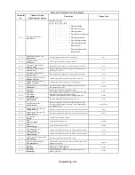
Analog Outputs
H4-01
Terminal FM Monitor
Selection
Terminal FM Sel
Selects which monitor will be output on terminals FM and FC.
1: Frequency Reference
100% = Maximum output frequency E1-04.
2: Output Frequency
100% = Maximum output frequency E1-04.
3: Output Current
100% = Drive rated current.
5: Motor Speed
100% = Maximum output frequency E1-04.
6: Output Voltage
100% = 200/400Vac depending on Drive voltage rating.
7: DC Bus Voltage
100% = 400/800Vdc depending on Drive voltage rating.
8: Output kWatts
100% = Drive rated power.
9: Torque Reference
100% = Motor rated torque.
15:Terminal A1 Input Level
100% = 10Vdc
16:Terminal A2 Input Level
100% = 10Vdc or 20mA
17:Terminal A3 Input Level
100% = 10Vdc
18:Motor Secondary Current
100% = Motor rated secondary current.
19:Motor Excitation Current
100% = Motor rated magnetizing current.
20:SFS Output
100% = Maximum output frequency E1-04.
21:ASR Input
100% = Maximum output frequency E1-04.
22:ASR Output
100% = Maximum output frequency E1-04.
24:PID Feedback
100% = Maximum output frequency E1-04.
26:Output Voltage Reference Vq
100% = E1-05, default 240V or 480V.
27:Output Voltage Reference Vd
100% = E1-05, default 240V or 480V.
31:Not Used
32:ACR q Output (100% = Motor rated secondary current)
33:ACR d Output (100% = Motor rated magnetizing current)
36:PID Input
100% = Maximum output frequency E1-04.
37:PID Output
100% = Maximum output frequency E1-04.
38:PID Setpoint
100% = Maximum output frequency E1-04.
44:ASR Output Without Filter
45:Feedforward Control Output
100% = Motor rated secondary current.
1 to 45
2
A
A
A
A
H4-02
Terminal FM Gain Setting
Terminal FM Gain
Sets terminal FM output level when selected monitor is at 100%.
0.0 to
1000.0
100.0%
Q
Q
Q
Q
H4-03
Terminal FM Bias Setting
Terminal FM Bias
Sets terminal FM output level when selected monitor is at 0%.
–110.0 to
110.0
0.0%
A
A
A
A
H4-04
Terminal AM Monitor Selec-
tion
Terminal AM Sel
Selects which monitor will be the output on terminals AM and FC.
Same function choices as H4-01.
1 to 53
3
A
A
A
A
H4-05
Terminal AM Gain Setting
Terminal AM Gain
Sets terminal AM output voltage (in percent of 10Vdc) when
selected monitor is at 100% output.
0.0 to
1000.0
50.0%
Q
Q
Q
Q
H4-06
Terminal AM Bias Setting
Terminal AM Bias
Sets terminal AM output voltage (in percent of 10Vdc) when
selected monitor is at 0% output.
–110.0 to
110.0
0.0%
A
A
A
A
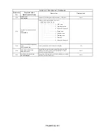
H4-07
Terminal FM Signal Level
Selection
AO Level Select 1
Selects the signal level of terminal FM.
0: 0 to 10Vdc
1: -10 to +10Vdc
2: 4 to 20mA*
0 or 2
0
A
A
A
A
H4-08
Terminal AM Signal Level
Selection
AO Level Select 2
Selects the signal level of terminal AM.
0: 0 to 10Vdc
1: -10 to +10Vdc
2: 4 to 20mA*
0 or 2
0
A
A
A
A
Denotes that parameter can be changed when the Drive is running. Note: Some analog outputs are control method dependent.
Table A.1 F7 Parameter List (Continued)
Parameter
No.
Parameter Name
Digital Operator Display
Description
Setting
Range
Factory
Setting
Control Method
V/F
V/F
w/
PG
Open
Loop
Vector
Flux
Vector
Summary of Contents for Varispeed f7
Page 1: ...F7 Drive Programming Manual Model CIMR F7U Document Number TM F7 02...
Page 2: ......
Page 8: ...vi Notes...
Page 158: ...Programming 150 Notes...


