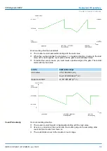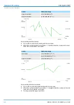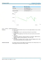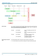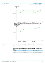
For not all inputs are available at the same time, you may set the input assignment for
every counter via the parameterization. For each counter the following inputs are avail-
able:
n
Channel
x
(A)
Pulse input for count signal res. track A of an encoder. Here you may connect
encoder with 1-, 2- or 4-tier evaluation.
n
Channel
x
(B)
Direction signal res. track B of the encoder. Via the parameterization you may invert
the direction signal.
n
Hardware gate
x
This input allows you to open the HW gate with a high peek and thus start a count
process. The usage of the HW gate may be parameterized.
n
Latch
x
With an edge 0-1 at Latch
x
the recent counter value is stored in a memory that you
may read at need.
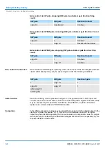
Every counter has an assigned output channel. The following behavior for the output
channel may be set via parameterization:
n
No comparison: Output is not controlled and is switched in the same way as a normal
output.
n
Count value
³
comparison value: Output is set as long as counter value
³
comparison
value.
n
Count value
£
comparison value: Output is set as long as counter value
£
comparison
value.
n
Pulse at comparison value: You can specify a pulse period for adaptation to the
actuators you are using. The output is set for the given pulse duration, as soon as the
counter reached the comparison value. If you have parameterized a main count direc-
tion the output is only set when reaching the comparison value from the main
counting direction. The maximum pulse duration may amount to 510ms. By setting 0
as pulse duration the output gets set as long as the comparison conditions are ful-
filled.
6.6.1.1
Parameter overview
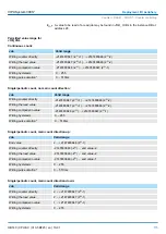
In the following the parameters are listed which may be used for counter configuration
during hardware configuration.
Here the short description of the counter function may be found. At
Comment
information
about the module such as purpose may be entered.
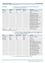
Here the start address of the in- /output periphery is set.
Here the interrupts the counter functions should trigger may be selected. You have the
following options:
n
None: There is no interrupt triggered.
n
Process: The counting function triggers a hardware interrupt.
n
Diagnostics and Process: With the CPU 313-5BF23 the diagnostic interrupt of the dig-
ital in-/output periphery is only supported in connection with "hardware interrupt lost".
Counter outputs
General
Addresses
Basic parameters
Count
VIPA System 300S
+
Deployment I/O periphery
Counter > Counter - Fast introduction
HB140 | CPU-SC | 313-5BF23 | en | 19-01
109


