6.5.1.1
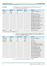
Address assignment
Input range
Sub module
Default address
Access
Assignment
DI24/DO16
124
Byte
Digital Input I+0.0 ... I+0.7
125
Byte
Digital Input I+1.0 ... I+1.7
126
Byte
Digital Input I+2.0 ... I+2.7
AI5/AO2
752
Word
Analog Input Channel 0
754
Word
Analog Input Channel 1
756
Word
Analog Input Channel 2
758
Word
Analog Input Channel 3
760
Word
Analog Input Channel 4
Counter
768
DInt
Channel 0: Count value / Frequency value
772
DInt
Channel 1: Count value / Frequency value
776
DInt
Channel 2: Count value / Frequency value
780
DInt
reserved
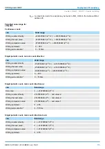
Output range
Sub module
Default address
Access
Assignment
DI24/DO16
124
Byte
Digital Output Q+0.0 ... Q+0.7
125
Byte
Digital Output Q+1.0 ... Q+1.7
AI5/AO2
752
Word
Analog Output Channel 0
754
Word
Analog Output Channel 1
Counter
768
DWord
reserved
772
DWord
reserved
776
DWord
reserved
780
DWord
reserved
6.5.2 Digital part - Parameterization
Parameters of the digital part may be set by means of the
DI24/DO16
submodule of the
CPU 313C from Siemens during hardware configuration. In the following all parameters
are specified, which may be used with the hardware configuration of the digital periphery.
This provides the short description of the digital periphery. At
Comment
information about
the module such as purpose may be entered.
At this register the start address of the in-/output periphery may be set.
Parameter data
General
Addresses
VIPA System 300S
+
Deployment I/O periphery
Digital part > Digital part - Parameterization
HB140 | CPU-SC | 313-5BF23 | en | 19-01
106


