6 MECHATROLINK Option Drive Parameters
YASKAWA
SIEP C730600 86F MECHATROLINK-II Technical Manual
19
*1
xx is the length (m).
Connect the terminator (model No.: JEPMC-W6022-E) on the end of the communication lines.
Note:
Maximum transmission distance is 50 m (164 ft). Minimum wiring distance between stations is 0.5 m (19.75 in).
■
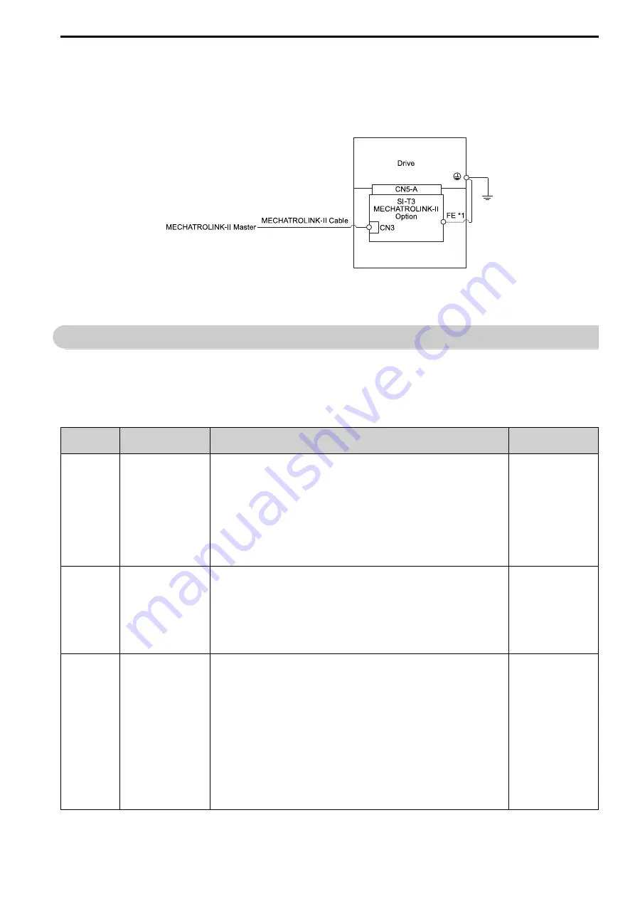
Option Connection Diagram
Figure 5.15 Option Connection Diagram
*1
Connect the provided ground wire for installations on 1000-series drives and GA500 drives. The ground wire is not necessary for
installation on GA700, GA800, CR700, or CH700 drives.
6
MECHATROLINK Option Drive Parameters
The parameters in the following table set the drive for operation with the option. Confirm proper setting of all
parameters in the following table before starting network communications.
Note:
Hex.: MEMOBUS addresses that you can use to change parameters over network communication are represented in hexadecimal
numbers.
No.
(Hex.)
Name
Description
Default
(Range)
b1-01
(0180)
Reference 1 Source
Selects the input method for frequency reference.
0 : Keypad
1 : Digital Input
2 : Memobus/Modbus Communications
3 : Option
4 : Pulse Train Input
Note:
•
Set
b1-02 = 3
to use the master device and serial communications to start and stop the drive.
Set
b1-01 = 3
to use the master device to control the frequency reference of the drive.
•
The default setting is different for different drives. Refer to the Peripheral Devices &
Options section of the drive instruction manual for more information.
1
(0 - 4)
b1-02
(0181)
Run Command 1 Source
Selects the input method for the Run command.
0 : Keypad
1 : Digital Input
2 : Memobus/Modbus Communications
3 : Option
Note:
Set
b1-02 = 3
to use the master device and serial communications to start and stop the drive.
Set
b1-01 = 3
to use the master device to control the frequency reference of the drive.
1
(0 - 3)
F6-01
(03A2)
Communication Error
Selection
Selects drive response when the drive detects a
bUS
error during communications with the option.
0 : Ramp to Stop
1 : Coast to Stop
2 : Fast Stop (Use C1-09)
3 : Alarm Only
4 : Alarm - Run at
d1-04
5 : Alarm - Ramp to Stop
Note:
•
When you set this parameter to
3
or
4
, the drive will continue operation after it detects a
fault. If you set this parameter to 3 or 4, make sure that you install an emergency stop
switch.
•
Refer to the drive manual to know if settings
4
and
5
are available. Settings 4 and 5 are
available in A1000 software versions PRG: 1021 and later.
•
The setting range for 1000-Series drives is different for different software versions. Refer to
the Peripheral Devices & Options section of the drive instruction manual for more
information.
1
(0 - 5)


