background image

5 Mechanical & Electrical Installation

YASKAWA

TOEPC71061687B Powerlink Option Installation Manual

23

9.

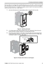
Reattach and secure the front cover of the drive (D) including the keypad (F).

Figure 5.11 Reinstall the Front Cover and Keypad

10.

Switch on the drive power supply.

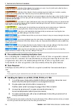
Installing the Option on a GA500

If you want to install the option card on a GA500 AC drive, you must use the Option Card
Mounting Kit (Model: JOHB-GA500). The installation procedure is described in the manual
that is shipped with that option.

Communication option cards can only be inserted into the

CN5-A

connector located on the

drive control board.

H

D

F

Tab

Keypad
connector

Summary of Contents for SI-EL3

Page 1: ...Powerlink Option Options Card for AC Drives and Regenerative Units Installation Manual Type SI EL3 SI EL3 V...

Page 2: ...This Page Intentionally Blank 2 YASKAWA TOEPC71061687B Powerlink Option Installation Manual...

Page 3: ...EDs 12 LEDs L A OUTand L A IN Ethernet Link Activity 1 and 2 12 S E LED 12 MS LED 13 Indicator Flash Rates 14 Connecting the Option Card 14 Communication Cable 15 Network Termination 15 5 Mechanical E...

Page 4: ...ooting 29 Communication Option Card Error Codes 29 Emergency Error Codes 30 Yaskawa specific SDO Abort Codes 37 Fault 38 Option Board Error Management 39 Minor Faults Alarms 40 8 Disposal 41 Disposal...

Page 5: ...to the final system design In all cases Yaskawa products should not be incorporated into a product or design as the exclusive or sole safety control function All control functions are designed to dyna...

Page 6: ...area around the drive motor and machine area and attach covers couplings shaft keys and machine loads before energizing the drive Failure to obey can cause death or serious injury WARNING Fire Hazard...

Page 7: ...NOTICE Do not connect or operate damaged equipment or equipment with missing parts Failure to obey can cause damage to the drive and connected equipment NOTICE Install fuses and an RCM RCD Failure to...

Page 8: ...uld cause a life or death situation loss of human life or a serious accident or physical injury About Registered Trademarks Powerlink is a registered trademark of Ethernet Powerlink Standardization Gr...

Page 9: ...re version see PRG on the nameplate of the AC drive or regenerative unit 3 Receiving Please perform the following tasks after receiving the Communication Option card Inspect the Communication Option c...

Page 10: ...cription Read the manual Obey the safety messages in the manual to prevent any kind of damage to humans or to the equipment Electrical Shock Hazard Correctly ground the drive before you turn on the EM...

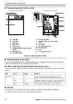
Page 11: ...ink Option Components Powerlink Option SI EL3 A Communication cable connector RJ45 B Ground terminal installation hole C Model number D Installation hole E LED S E F LED MS G LED L A 2 H LED L A 1 I C...

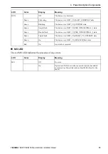
Page 12: ...tor Specification LEDs L A OUT and L A IN Ethernet Link Activity 1 and 2 The Link Activity indicators show the status of the physical link and show activity on the link period LED Color Display Meanin...

Page 13: ...ash The device is in NMT_CS_PRE_OPERATIONAL_1 state Green Double flash The device is in NMT_CS_PRE_OPERATIONAL_2 state Green Triple flash The device is in NMT_CS_READY_TO_OPERATE state Green On The de...

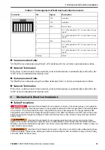
Page 14: ...he Communication Option card is connected to the network using a RJ45 connector flickering on 50 ms 200 ms 200 ms 200 ms 200 ms 200 ms 200 ms 200 ms 200 ms 200 ms 200 ms 200 ms 200 ms 200 ms 200 ms 20...

Page 15: ...card 5 Mechanical Electrical Installation Safety Precautions DANGER Electrical Shock Hazard Do not examine connect or disconnect wiring on an energized drive Before servicing disconnect all power to...

Page 16: ...interference and unsatisfactory system performance NOTICE Do not change the drive circuitry Failure to obey can cause damage to the drive and will void warranty Yaskawa is not responsible for modifica...

Page 17: ...erator I LED labels J Front cover Figure 5 1 Installing the Option Card on a A1000 D1000 R1000 or U1000 5 Prepare the RJ45 network cable connectors For drives CIMR Ax2A0004 to 2A0040 and 4A0002 to 4A0...

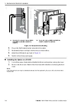
Page 18: ...ctor to the option 7 Reinstall the front cover back onto the drive as it was before 8 Attach the LED label I as shown in Figure 5 1 9 Switch on the drive power supply Installing the Option on a V1000...

Page 19: ...ossible cable for ground connection 4 Re attach the bottom cover 5 Connect the Communication Option card to the drive Properly secure the tabs on the left and right side of the Communication Option ca...

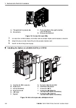
Page 20: ...ar connector 8 Attach the cover to the front of the Communication Option card 9 Switch on the drive power supply Installing the Option on a GA800 GA700 or CR700 A Insertion for CN5 connector B Option...

Page 21: ...on the drive control board 1 Affix the LED label E in the appropriate position on the drive front cover D Figure 5 7 Affix the LED Label 2 Turn off the power Wait until the CHARGE LED turns off and th...

Page 22: ...e The option package ships with three screws and a ground wire for installation on other drive series Do not use the ground wire or the extra screw Figure 5 10 Insert the Option Card 6 Firmly connect...

Page 23: ...Keypad 10 Switch on the drive power supply Installing the Option on a GA500 If you want to install the option card on a GA500 AC drive you must use the Option Card Mounting Kit Model JOHB GA500 The i...

Page 24: ...A J Connector CN5 B Not for communication option installation K Connector CN5 C Not for communication option installation Figure 5 12 Q2A Components with Option Card The procedures for removing and r...

Page 25: ...urn off the power Wait until the CHARGE LED turns off and then remove the cover Refer to the drive manual for direction on removing the front cover 3 Move the keypad connector to the holder on the dri...

Page 26: ...d wire The option package ships with three screws and a ground wire for installation on other drive series Do not use the ground wire or the extra screw Figure 5 16 Insert the Option Card 6 Firmly con...

Page 27: ...manual that is shipped with that option Communication option cards can only be inserted into the CN5 A connector located on the drive control board XDD File For easy network implementation of drives...

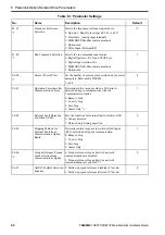
Page 28: ...ction after Communications Error Determines drive response when a bUS error is detected during communications with the Communication Option 0 Ramp to Stop 1 Coast to Stop 2 Fast Stop 3 Alarm Only 3 1...

Page 29: ...If set to 3 then the drive will continue to operate when an EF0 fault is detected Take proper safety measures such as installing an emergency stop switch 4 This parameter might not appear in certain d...

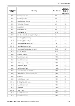
Page 30: ...3221 SoftCharge Bypass Circuit Fault Uv3 04 2340 Out Short Circuit or IGBT Fault SC 05 2330 Ground Fault GF 06 2220 Overcurrent oC 07 3210 DC Bus Overvoltage ov 08 4280 Heatsink Overheat oH 09 4210 H...

Page 31: ...ion Fault CE 21 FF04 Option Communication Error bUS 22 FF05 Control Fault CF 25 8313 Zero Servo Fault SvE 26 5481 Option Card External Fault EF0 27 FF06 PID Feedback Loss FbL 28 FF07 Undertorque Detec...

Page 32: ...Detection 1 oL5 44 FF20 Mechanical Weakening Detection 2 UL5 45 FF21 Current Offset Fault CoF 46 FF22 PLC Detection Error 1 PE1 47 FF23 PLC Detection Error 2 PE2 48 FF24 DriveWorksEZ Fault dWFL 49 63...

Page 33: ...Power Supply Frequency Fault Fdv 68 FF3D Phase Order Detection Fault SrC 69 FF3E Power Supply Undervoltage Pre Alarm PAUv 6B FF3F AC Fuse Blowout FUA 70 FF40 Resonance Detection vrE 71 FF41 Control C...

Page 34: ...de Error CPF31 A0 FF5C ASIC Start up Error CPF32 A1 FF5D Watchdog Circuit Exception Circuit Fault CPF33 A2 FF5E ASIC Power Clock Error CPF34 A3 FF5F External A D Conversion Failure CPF35 A4 FF60 ASIC...

Page 35: ...rt CN5 A oFA17 118 FF78 Comm ID Error oFA30 131 FF79 Model Code Error oFA31 132 FF7A Checksum Error oFA32 133 FF7B Comm option timeout waiting for response oFA33 134 FF7C MEMOBUS Modbus communications...

Page 36: ...234 FF97 MEMOBUS Modbus communications timeout oFb34 235 FF98 Drive timeout waiting for response oFb35 236 FF99 CI Check Error oFb36 237 FF9A Drive timeout waiting for response oFb37 238 FF9B Control...

Page 37: ...at Option Port oFC52 353 FFB1 Option Card Error Occurred at Option Port oFC53 354 FFB2 Option Card Error Occurred at Option Port oFC54 355 FFB3 Option Card Error Occurred at Option Port oFC55 356 FFB4...

Page 38: ...drive did not receive a signal from the controller The communications cable wiring is incorrect Correct wiring errors There is a short circuit in the communications cable or the communications cable...

Page 39: ...rect connector Note DO A3 AO A3 PG B3 and PG X3 options can connect to connector CN5 B To connect only one PG option card use the CN5 C connector oFb02 Duplicate Options The same option cards or the s...
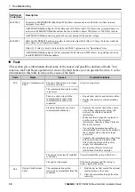
Page 40: ...r Indication Possible Solution Initial power up sequence not completed within 10 seconds Possible cause Drive is not processing the internal interface protocol Drive does not support this communicatio...

Page 41: ...ng is faulty there is a short circuit or something is not connected properly Correct any wiring errors EEPROM checksum error If these errors occur the object dictionary will be reset to its default va...

Page 42: ...l and electronic equipment EEE Do not discard the product with usual waste 9 Specifications Item Specification Model SI EL3 For V1000 SI EL3 V Communication Profile DSP 301 Ver 4 02 DSP 402 Ver 1 1 Ve...

Page 43: ...ry Date of Publication Revi sion Num ber Section Revised Content September 2013 A First Edition May 2020 B All Updated with new supported AC drives and regenerative units Updated software versions Upd...

Page 44: ...0085 U S A Phone 1 800 YASKAWA 927 5292 or 1 847 887 7000 Fax 1 847 887 7310 http www yaskawa com In the event that the end user of this product is to be the military and said product is to be employe...

Reviews: