5 Mechanical & Electrical Installation
YASKAWA
TOEPC71061687B Powerlink Option Installation Manual
17
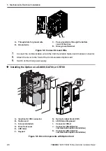
A - Connector CN5-C
B - Connector CN5-B
C - Connector CN5-A
D - Drive grounding terminal (FE)
E -
Option cards
F -
Ground wire
G - Opening for cable lines (use cutter to
create the opening)
H - Operator
I -
LED labels
J -
Front cover
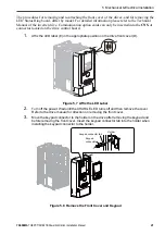
Figure 5.1 Installing the Option Card on a A1000, D1000, R1000 or U1000
5.
Prepare the RJ45 network cable connectors.
For drives CIMR-Ax2A0004 to 2A0040 and 4A0002 to 4A0023: the network cable
should be routed to the outside through the openings at the left side (G) of the front
cover. Make sure no sharp edges remain.
For drives 2A0056 to 2A0211, and 4A0031 to 0165: enough space to keep all wiring
inside the unit is available.
F
A
E
H
I
B
C
D
G
J
2
1

