12
YASKAWA
TOEPC71061687B Powerlink Option Installation Manual
◆
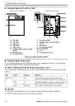
Powerlink Option SI-EL3/V for V1000
A - LED (MS)
B - LED (S/E)
C - LED (L/A 1)
D - LED (L/A 2)
E -
Option Cover
F -
Communication cable connector
(RJ45)
G - Mounting clip
H - Connector (CN5)
I -
Option Card PCB
J -
Attachment screw hole for option
cover
K - Nameplate
L -
Ground terminal (FE)
M - Mounting clip
N - Wire
O - Through-hole for wire
Figure 4.2 Option Card for V1000
◆
Powerlink Option Status LEDs
The Powerlink Option has four LEDs that indicate the communication status. The indications
conform with DS303, Part 3: Indicator Specification.
■
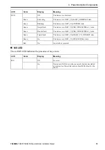
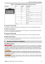
LEDs L/A OUT and L/A IN: Ethernet Link/Activity 1 and 2
The Link/Activity indicators show the status of the physical link and show activity on the link
period.
LED
Color
Display
Meaning
Link Activity
1/2
–
Off
No link. The communication cable is not physically
connected. The communication controller is not started up.
Green
On
The module is connected to Ethernet. A communication cable
is physically connected, but no data is being exchanged.
Green
Flickering
There is traffic on Ethernet, data is being exchanged.
■
S/E LED
A green lit S/E LED indicates the status of the communication network state machine.
A red lit S/E LED indicates error on the EPL network side.
H
G
J
I
M
L
N
O
K
F
FE
1
2
B
A
C
D
E
Powerlink with cover attached
Powerlink with cover removed
Underside


