


APPLICATIONS OF
Σ
-SERIES PRODUCTS
3.8.4
Using Regenerative Units
cont.
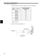
150
4)
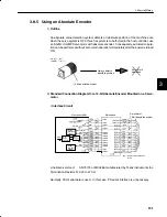
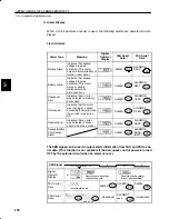
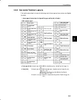
Connecting a Regenerative Unit
The standard connection diagram for a regenerative unit is shown below.
Single-phase
200-230 VAC or
100-115 VAC
DR2 Servopack (DR2-A3A, A5A, 01A or 02A)
Alarm
Alarm
Regenerative unit
Servomotor
Photocoupler
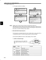
a) A regenerative unit has the following fault detection functions:
•
Detecting broken wiring in a regenerative resistor
•
Detecting faults in a regenerative transistor
•
Detecting overvoltage
b) When one of these fault detection functions operates, the internal alarm relay is actu-
ated. Then, the circuit between output terminals C1 and C2 is opened.
c) Form a sequence so that the Servopack main power is turned OFF when the alarm
relay is actuated.
d) Once the alarm relay is actuated, it takes two or three seconds until the system returns
to the normal state. This time is required for the main capacitor inside the Servopack
to discharge electricity.
3


