


3.2
Setting User Constants According to Host Controller
69
3.2.2 Inputting Position Reference
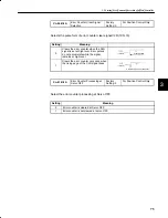
1) Using the following memory switch, select the position control.
Cn-02 Bit B
Selection of Speed/Torque
Control or Position Control
Factory
Setting: 0
For Speed/Torque Control
and Position Control
Select the control mode (speed/torque control or position control) by bit B of memory
switch Cn-02.
Setting
Meaning
0
Selects speed or torque control.
Select the control form by bits A and B of memory switch Cn-01.
1
Selects position control.
Note
For the memory switch Cn-02, always turn the power OFF and then ON after
changing the setting. This makes the new setting valid.
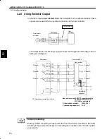
2) Input a position reference by using the following input signal “reference pulse input.”
Since there are several specifications for input signal, select reference input for the sys-
tem to be created.
Inputs a move reference by pulse
input.
Position reference can correspond
to the following three types of out-
put form:
•
Line driver output
•
+12V Open collector output
•
+5V Open collector output
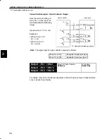
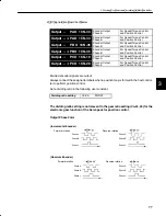
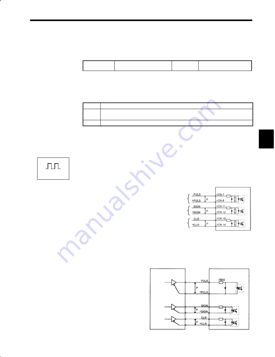
Connection Example 1: Line Driver Output
Line Driver Used:
SN75174 manufactured by
Texas Instruments Inc., or
MC3487 or equivalent.
3
Positions
Reference pulse
input
Reference sign
input
Error counter
clear input
Servopack
↕
P: Represents twisted-pair cables
PHOTOCOUPLER
Host controller
Line driver
Servopack
Photocoupler
1CN-7
1CN-8
1CN-11
1CN-12
1CN-15
1CN-14


