background image

SERVO SELECTION AND DATA SHEETS

5.1.3


Digital Operator

216

5.1.3 Digital Operator

1) Use the following digital operator (hand-held type) for operation.

JUSP-OP02A-1 (Hand-held Type)

Use held in the hand while connected
with the 1 m cable supplied.

Note

Mount type digital operator (JUSP-OP03A) cannot be
used for DR2 Servopack.

Instead of digital operator, also personal computer (IBM PC)
can be used to monitor or set the user constants.
For details, refer to the manual ”Operation Manual for
Personal Computer Monitoring Software”
(Manual No. SIE-S800-15.5).

5

JUSP-OP03A (Mount Type)

.

Summary of Contents for SGM-A3

Page 1: ...YASKAWA Series SGM SGMP DR2 USER S MANUAL YASKAWA MANUAL NO TSE S800 17D AC Servomotors and Driver SGM SGMP Servomotors DR2 Servopack...

Page 2: ...ut and how to design install operate and maintain a servo system Keep this manual in a convenient location and refer to it whenever necessary in operating and maintaining the servo system YASKAWA ELEC...

Page 3: ...or CAUTION WARNING Indicatesapotentiallyhazardoussituationwhich ifnot avoided couldresult in deathor serious personalinju ry CAUTION Indicates a potentially hazardous situation which if not avoided m...

Page 4: ...hock may result S After turning OFF power wait at least five minutes before servicing the product Otherwise residual electric charges may result in electric shock CAUTION RECEIVING S Use the specified...

Page 5: ...un failure S Before starting operation with a load connected make sure emergency stop procedures are in place Failure to observe this caution may result in personal injury S During operation do not to...

Page 6: ...Chapters explaining maintenance For users who are going to maintain and troubleshoot Series products Chapter Title Page Area CHAPTER 1 For First time Users of AC Servos 1 A B Provides an overview of...

Page 7: ...423 A B C B Servo Adjustment 429 B C C List of I O Signals 445 A B C D List of User Constants 465 B C E List of Alarm Displays 477 B C F Relationship between Reference Forms and User Constants 481 B...

Page 8: ...that need to be explained to users who are not very familiar with servo systems or electronic devices and technical terms specific to Series Ser vos that need to be explained in descriptions of funct...

Page 9: ...edwithrespecttotheuseoftheinformationcontainedherein Moreover becauseYaskawa is constantly striving to improve its high quality products the information contained in this manual is subject to change w...

Page 10: ...Constants Required and Input Signals 47 CHAPTER 3 APPLICATIONS OF SERIES PRODUCTS 49 3 1 Setting User Constants According to Machine Characteristics 52 3 1 1 Changing the Direction of Motor Rotation 5...

Page 11: ...and Alarm Code Output 128 3 7 2 Using Servo ON Input Signal 132 3 7 3 Using Positioning Complete Signal 133 3 7 4 Using Speed Coincidence Output Signal 134 3 7 5 Using Running Output Signal 136 3 7 6...

Page 12: ...Overload Characteristics 239 5 3 4 Starting Time and Stopping Time 240 5 3 5 Load Inertia 241 5 3 6 Overhanging Loads 246 5 4 Series Dimensional Drawings 247 5 4 1 Servomotor Dimensional Drawings 247...

Page 13: ...by EU 417 7 2 Measures to Satisfy the Requirements of EMC Directive 418 7 2 1 Applicable Servomotor 418 7 2 2 Applicable Noise Filter 418 7 2 3 Motor Cables 419 7 2 4 Encoder Cables 419 7 2 5 Control...

Page 14: ...CONTENTS xv E List of Alarm Displays 477 F Relationship between Reference Forms and User Constants 481 G Reviewing the Full closed Loop Specifications 489 INDEX 497...

Page 15: ...of a servo mechanism and basic technical terms relating to servos Users who already have experience in using a servo should also take a look at this chapter to understand the features of Series AC Se...

Page 16: ...rol mechanism that monitors physical quantities such as specified positions In short a servo mechanism is like a servant who does tasks faithfully and quickly according to his master s instructions In...

Page 17: ...is a system to control the output data to match the specified input data If for example the specified position changes the servo system will reflect the changes In the above example input data is def...

Page 18: ...g Servomotor General servomotors or Yaskawa SGM SGMP Servomotors In some cases a position detector encoder is included in a servomotor Servopack Trademark of Yaskawa servo amplifier DR2 Servopack Serv...

Page 19: ...This includes a drive system that transmits torque from a servo motor 2 Servomotor A main actuator that moves a controlled system Two types are available AC servomotor and DC servomotor 3 Detector A...

Page 20: ...is drive system is widely used for ma chining tools Timing Belt Trapezoidal Screw Thread A timing belt is a coupling device that allows the power transmission ratio to be set freely and that has no pl...

Page 21: ...ive maintenance inspect and replace parts at regular intervals For details refer to Chapter 6 Inspection Maintenance and Troubleshooting b AC Servomotor AC servomotors are divided into two types synch...

Page 22: ...as a certain length e g 0 001 mm it can be used as a position detector However this encoder does not detect an absolute position and merely outputs a pulse train Hence zero return operation must be p...

Page 23: ...generates a differential signal The control function amplifies and transforms the differential signal In other words it performs proportional P control or proportional integral PI control It is not im...

Page 24: ...ference a position control loop may be formed in the host controller when a position feedback signal is received Yaskawa PROGIC 8 is a typical host controller TERMS PROGIC 8 A programmable machine con...

Page 25: ...W 750 W 0 04 HP 0 07 HP 0 13 HP 0 27 HP 0 53 HP 1 01 HP 2 DR2 Servopacks can perform speed torque or position control Select the control mode by set ting of the user constant Cn 02 memory switch Speed...

Page 26: ...or Position feedback Encoder Position control loop Position feedback Speed As shown in the figure above a position control loop is formed in the host controller The host controller compares a position...

Page 27: ...ert Torque current feedback Pulse train Servomotor Position feedback Encoder Analog voltage Set the user constants for Servopack to switch between the following torque control modes 1 Controlling serv...

Page 28: ...rm positioning or interpolation This type of Servopack contains a position control loop User constants can be used to select either of the following pulse trains 1 Code and pulse train 2 Two phase pul...

Page 29: ...2 2 Installing the Servomotor 19 2 2 3 Installing the Servopack 22 2 3 Connection and Wiring 25 2 3 1 Connecting to Peripheral Devices 25 2 3 2 Main Circuit Wiring and Power ON Sequence 28 2 3 3 Exam...

Page 30: ...ection to the commercial power supply will damage the Servomotor Do not change wiring when power is ON Always turn the power OFF before connecting or disconnecting a connector Except for Digital Opera...

Page 31: ...ls securely Use a fast response type ground fault detector For a ground fault detector always use a fast re sponse type or one designed for PWM inverters Do not use a time delay type Do not perform co...

Page 32: ...all appearance and check for damage or scratches resulting from transportation Check screws for looseness Check for looseness by using a screwdriver as necessary If any of the above items are faulty o...

Page 33: ...can be installed either horizontally or vertically However if the Servomotor is installed incorrectly or in an inappropriate location the service life will be shortened or unexpected problems will oc...

Page 34: ...wn below Measure this distance at four different positions in the circumference The difference between the maximum and minimum measurements must be 0 03 mm or less Turn together with couplings Measure...

Page 35: ...392 88 147 33 35 1 43 Servomotor with absolute encoder Motor Type Allowable Radial Load Fr N lb Allowable Thrust Load Fs N lb LR mm in Reference Drawing SGM A3 49 11 19 4 20 0 82 SGM A5 68 15 19 4 20...

Page 36: ...from the heating unit and a temperature rise caused by convection so that the temperature around the periphery of the Servopack does not exceed 55 C When installed near a source of vibration Install...

Page 37: ...panel observe the following installation method Fan 50 mm or more Fin 30 mm or more 10 mm or more Fan 50 mm or more a Install Servopack perpendicularly so that the front panel containing connectors fa...

Page 38: ...ll cooling fans above the Servopacks to prevent the temperature around each Servopack from increasing excessively and also to maintain the temperature inside the control panel evenly d Maintain the fo...

Page 39: ...tandard example of connecting Series products to peripheral de vices and briefly explains how to connect to each peripheral device NOTE Read the following notes before wiring Connect only one cable to...

Page 40: ...perator Allows the user to set user constants or operation references and display operation status or alarm status Power supply Single phase 200 or 100 V Connector kits for pulse generator PG and for...

Page 41: ...is compatible with most P L C motion controllers and indexers References are input as analog signals or pulse trains 1CN connector kit Type DP9420010 On Servomotor side On Servopack side This connect...

Page 42: ...the name and description of each main circuit terminal Terminal Symbol Name Description L1 L2 Main circuit AC input Single phase 200 to 230 VAC 50 60Hz 1 10 15 L N Control power supply input Single ph...

Page 43: ...wer is turned ON This operation is required to initialize the Servopack Servo alarm ALM output signal Power supply NOTE D After turning the power OFF do not touch the power terminals for 5 minutes Hig...

Page 44: ...y referring to technical documentation for the host controller NOTE This sub section describes signals related to the DR2 Servopack only For other signals refer to the relevant technical documentation...

Page 45: ...eed Control MADE BY YASKAWA SERVO NORMAL DECEL LS ALARM SERVOPACK 1 These signals are output for approximately two seconds when the power is turned ON Take this into consideration when designing a pow...

Page 46: ...vopack DECEL LS 1 These signals are output for approximately two seconds when the power is turned ON Take this into consideration when designing a power ON sequence Relay 1Ry is used to stop main circ...

Page 47: ...wer is turned ON Take this into consideration when designing a power ON sequence Relay 1Ry is used to stop main circuit power supply to Servopack Note The signals shown here are applicable only to OMR...

Page 48: ...1 These signals are output for approximately two seconds when the power is turned ON Take this into consideration when designing a power ON sequence Relay 1Ry is used to stop main circuit power supply...

Page 49: ...F ERENCE 1 These signals are output for approximately two seconds when the power is turned ON Take this into consideration when designing a power ON sequence Relay 1Ry is used to stop main circuit pow...

Page 50: ...tected ON when positioning is stopped EXTERNAL POWER SUPPLY 24V 1 These signals are output for approximately two seconds when the power is turned ON Take this into consideration when designing a power...

Page 51: ...nstants Required and Input Signals 47 2 4 1 Test Run in Two Steps Conduct the test run when wiring is complete Generally conducting a test run for servo drives can be difficult However by following th...

Page 52: ...O signals Step 2 Conducting a test run with the motor and machine connected Adjust Servopack according to machine characteristics Speed adjustment by autotuning Connect to the machine Connect to the m...

Page 53: ...to prevent it from moving during operation Alter natively install the servomotor on the machine and disconnect couplings and belts 2 Disconnect connector 1CN then check the motor wiring in the power...

Page 54: ...1 Turn the power OFF 2 Return the alarm signal circuit shorted in the above step 3 to its original state 3 Connect connector 1CN 4 Turn the power ON again 7 Check input signals Check the input signal...

Page 55: ...mal the motor is turned ON and the Digital Operator displays the data as shown in the figure If an alarm dis play appears take appropriate action as de scribed in Appendix E List of Alarm Displays 9 O...

Page 56: ...nce offset value as described in Section 4 2 4 Reference Offset Automatic Adjustment 4 To change motor speed or the direction of rotation reset the user constants shown below Cn 03 Speed reference gai...

Page 57: ...host con troller specifications In this case check the wiring and review the user constant settings then repeat step 1 Refer to Appendix E List of Alarm Displays and Appendix D List of User Constants...

Page 58: ...3 Perform autotuning Tune the Servopack according to the machine characteristics Refer to 4 2 3 Autotuning 4 Operate by reference input As in step 1 conducting a test run for motor without load perfo...

Page 59: ...ding brake operation for a servomotor with brake Vertical axis Axis to which external force is applied Servomotor Holding brake Prevents the motor from rotating due to gravity External force Servomoto...

Page 60: ...m host controller Motor speed Check the motor speed as follows D Use the speed monitor Un 00 of the digital operator D Run the motor at low speed For example input a speed reference of 60 r min and ch...

Page 61: ...direction of rotation differs from the actual direction of rotation the wiring may be incorrect In this case recheck the wiring and correct it accordingly Then if the direction of rotation is to be re...

Page 62: ...nts According to Host Controller 64 3 2 1 Inputting Speed Reference 64 3 2 2 Inputting Position Reference 69 3 2 3 Using Encoder Output 76 3 2 4 Using Contact I O Signals 80 3 2 5 Using Electronic Gea...

Page 63: ...ional Control 120 3 6 5 Setting Speed Bias 121 3 6 6 Using Mode Switch 122 3 7 Forming a Protective Sequence 128 3 7 1 Using Servo Alarm Output and Alarm Code Output 128 3 7 2 Using Servo ON Input Sig...

Page 64: ...8 Connector Ter minal Layouts I O signals Host controller external circuit 3 For a list of user constants refer to Appendix D List of User Constants 4 User constants are divided into the following two...

Page 65: ...s a reverse rotation mode in which the direction of rotation can be reversed without altering the servomotor wiring With the standard setting forward rotation is defined as counterclockwise CCW rotati...

Page 66: ...of rotation Setting Meaning 0 Forward rotation is defined as counterclockwise rotation when viewed from the drive end Standard setting 1 Forward rotation is defined as clockwise rotation when viewed...

Page 67: ...put N OT 1CN 43 Reverse Rotation Prohibited Reverse Overtravel For Speed Torque Control and Position Control Inputs terminals for overtravel limit switch For linear motion connect a limit switch to pr...

Page 68: ...horting 1CN 42 to 0 V Bit 3 0 Uses the N OT input signal for prohibiting reverse rotation Reverse rotation is prohibited when 1CN 17 is open Reverse rotation is allowed when 1CN 43 is at 0 V Bit 3 1 D...

Page 69: ...the input signal for prohibiting forward or reverse rotation is to be used Specifies a torque value in terms of a percentage of the rated torque Cn 01 Bit 6 How to Stop Motor at Servo OFF Factory Set...

Page 70: ...ue after the motor moves the machine to a specified position D Torque control Level 3 To always control output torque not speed Level 4 To alternately use speed control and torque control This section...

Page 71: ...torque limit val ue will result in torque shortage at ac celeration or deceleration Using CLT CLT Signals This section describes how to use contact output signals CLT CLT as a torque limit output sign...

Page 72: ...t signals CLT 1CN 25 and CLT 1CN 26 Setting Meaning 0 Uses CLT CLT output signals as a torque limit output signal Compares the DR2 Servopack internal torque current reference with the preset value Pre...

Page 73: ...l Torque restriction does not apply during forward rotation N CL ON 1CN 46 is at low level Torque restriction applies during reverse rotation Limit value Cn 19 N CL OFF 1CN 46 is at high level Torque...

Page 74: ...orque restriction by analog voltage reference refer to 3 2 9 Using Torque Restriction by Analog Voltage Reference Using P CL and N CL Signals This section describes how to use input signals P CL and N...

Page 75: ...Speed Control Selection Factory Setting 0 For Speed Torque Control and Position Control Prohibits the contact input speed control function If the contact input speed control function is used the conte...

Page 76: ...3 1 Setting User Constants According to Machine Characteristics 63 Handling of the CLT CLT signals are the same as for level 1 internal torque limit Refer to Using CLT CLT Signals on page 58 3...

Page 77: ...ed Reference 1 Using the following memory switch select the speed torque control Cn 02 Bit B Selection of Speed Torque Control or Position Control Factory Setting 0 For Speed Torque Control and Positi...

Page 78: ...rcuit See the figure on the right For noise control always use twisted pair cables Recommended Variable Resistor for Speed Setting Type 25HP 10B manufactured by Sakae Tsushin Kogyo Co Ltd When positio...

Page 79: ...t signal P CON to specify one of the four modes shown below Cn 01 Bit A Control Mode Selection Factory Setting 0 For Speed Torque Control Only Cn 01 Bit B Control Mode Selection Factory Setting 0 For...

Page 80: ...This speed control allows the zero clamp function to be set when the motor stops D Speed reference is input from V REF 1CN 5 D P CON 1CN 41 signal is used to turn the zero clamp function ON or OFF Zer...

Page 81: ...ching between torque control and speed control Torque control II 1 Changing the direction of rotation during contact input speed control 4 Adjust the speed reference gain using the following user cons...

Page 82: ...fter changing the setting This makes the new setting valid 2 Input a position reference by using the following input signal reference pulse input Since there are several specifications for input signa...

Page 83: ...e signal logic for open collector output is as follows When Tr1 is ON Equivalent to high level input When Tr1 is OFF Equivalent to low level input Output PL1 1CN 3 Power for Open Collector Reference F...

Page 84: ...Control Only Input SIGN 1CN 11 Reference Sign Input For Position Control Only Input SIGN 1CN 12 Reference Sign Input For Position Control Only The motor only rotates at an angle proportional to the in...

Page 85: ...1CN 7 1CN 11 1CN 7 1CN 11 0 0 1 CW 1 pulse CCW pulse 1CN 7 1CN 11 1CN 7 1CN 11 0 0 0 Sign pulse train 1CN 7 1CN 11 1CN 7 1CN 11 1 Nega 0 1 0 1 Two phase pulse train with 1CN 7 1CN 11 1CN 7 1CN 11 Neg...

Page 86: ...al Generation Timing Servo ON Base block Sign pulse train Release t1 30 ms t2 6 ms When user constant Cn 12 is set to 0 t3 40 ms PG pulse t4 t5 t6 2 ms t7 20 s Note The interval from the time the serv...

Page 87: ...behind phase B User constant Cn 02 bits 3 4 and 5 is used to switch the input pulse multiplier mode CCW pulse CW pulse Maximum reference frequency 450 kpps CCW pulse CW pulse reference reference 4 The...

Page 88: ...is set at high level Error pulses do not accumulate while the signal remains at high level Cleared state 1CN 15 1 Clears the error counter only once when the rising edge of the CLR signal rises Clear...

Page 89: ...line according to the fol lowing circuit diagram Servopack Host controller Line receiver Choke coil Smoothing capacitor Line receiver used SN75175 manufactured by Texas Instruments Inc or MC3486 or eq...

Page 90: ...ition Control Output PCO 1CN 20 Encoder Output Phase C For Speed Torque Control and Position Control Divided encoder signals are output Always connect these signal terminals when a position loop is fo...

Page 91: ...absolute encoders For details refer to 3 8 5 Using an Absolute Encoder Output SG 1CN 1 Signal Ground for Encoder Output For Speed Torque Control and Position Control Output FG 1CN 50 Frame Ground For...

Page 92: ...in this user constant Set this value ac cording to the reference unit of the machine or controller to be used The setting range varies according to the encoder used Motor Type Number of Encoder Pulse...

Page 93: ...pply separately There are no power terminals to which the DR2 Servopack outputs signals exter nally External Power Supply 24 1 VDC 50 mA or more Yaskawa recommends that this external power supply be t...

Page 94: ...ut current 20 mA DC Photocoupler Host controller I O power supply Note Provide an external I O power supply separately There are no power terminals to which the DR2 Servopack outputs signals exter nal...

Page 95: ...653 pulses A total of 13653 pulses must be input as a reference the host controller needs to make this calculation Machine conditions and reference unit must be defined for the electronic gear functio...

Page 96: ...it is 0 001 mm 5 0 001 5 000 reference units Ball Screw Disc Table Belt Pulley Load shaft 1 revolution P Pitch Reference unit P 1 revolution Reference unit 360 Load shaft D Pulley diameter Load shaft...

Page 97: ...o Numerator Unit None Setting Range 1 to 65535 Factory Setting 4 For Position Control Only Cn 25 RATA Electronic Gear Ratio Denominator Unit None Setting Range 1 to 65535 Factory Setting 1 For Positio...

Page 98: ...of load shaft Preset values 24576 3600 Cn 24 Cn 25 0 1 360 3600 Electronic gear ratio B A 2048 4 3 3600 1 Cn 24 Cn 25 Belt Pulley Pulley diameter 100 mm Absolute encoder 1024 pulses per revolution Cn...

Page 99: ...device or pulse generator is required The motor is operated at the speed set in the user constant P CON 1CN 41 P CL N CL 1CN 45 1CN 46 2 To use the contact input speed control function perform Steps a...

Page 100: ...or Speed Torque Control and Position Control Cn 20 SPEED2 2nd Speed Contact Input Speed Control Unit r min Setting Range 0 to Maximum Speed Factory Setting 200 For Speed Torque Control and Position Co...

Page 101: ...peration The following input signals are used to start and stop the motor Input P CL 1CN 45 Speed Selection 1 Forward External Torque Limit Input For Speed Torque Control and Position Control Input N...

Page 102: ...ue limit input Input signal P CON is used to specify the direction of motor rotation Input P CON 1CN 41 Proportional Control etc For Speed Torque Control and Position Control a Contact Input Speed Con...

Page 103: ...t function is not available when pulse reference input is used For the position control type if contact input speed control mode is switched to pulse reference input mode when the motor is running at...

Page 104: ...ect level 3 torque control I or level 4 torque con trol II Cn 01 Bit A Control Mode Selection Factory Setting 0 For Speed Torque Control Only Cn 01 Bit B Control Mode Selection Factory Setting 0 For S...

Page 105: ...Switching between speed and torque reference 1CN 5 1CN 9 1CN 41 When 1CN 41 is open Torque control When 1CN 41 is at 0 V Speed control For Torque Control when P CON is OFF 1 1 D T REF reference contr...

Page 106: ...t il f d t l 1 Speed reference Torque feed forward For details of speed control with torque feed forward refer to 3 2 8 Using Torque Feed forward Function 0 1 Speed control with torque limit by analog...

Page 107: ...ted pair cables Example of Variable Resistor for Speed Setting Type 25HP 10B manufactured by Sakae Tsushin Kogyo Co Ltd Input V REF 1CN 5 Speed Reference Input or Speed Limit Input For Speed Torque Co...

Page 108: ...switch Cn 01 to 1 Input P CON 1CN 41 Proportional Control etc For Speed Torque Control and Position Control The function of this input signal varies according to the memory switch setting Cn 02 Bit 2...

Page 109: ...4 TCRLMT Speed Limit for Torque Control I Unit r min Setting Range 0 to Maximum Speed Factory Setting Maximum Speed For Speed Torque Control Only Sets a motor speed limit value in this constant when t...

Page 110: ...and T REF 1CN 9 1CN 10 respectively Host controller Servopack Diffe renti ation Position reference Current loop Servomotor Speed calculation Frequency dividing Encoder KP Position loop gain KFF Feed...

Page 111: ...icted to 100 rated torque Cn 13 TCRFGN Torque Reference Gain Unit 0 1 V Rated Torque Setting Range 10 to 100 Factory Setting 30 For Speed Torque Control Only 3 2 9 Using Torque Restriction by Analog V...

Page 112: ...everse rotation The same setting applies to both forward and reverse rotation Setting Meaning 0 Uses the T REF terminal as a torque reference or torque feed forward reference input terminal 1 Uses the...

Page 113: ...ntrol for speed loop PI con trol is always used Servopack Reference pulse Cn 01 bit F Error counter Feedback pulse Schematic Block Diagram for INHIBIT Function P CON 2 How to Use Reference Pulse Inhib...

Page 114: ...rence pulse input filter inside the Servopack according to the output form of reference pulses from the host controller 2 How to Use Reference Pulse Input Filter Set the following memory switch accord...

Page 115: ...3V 100 torque VTG M Speed monitor output 3V 1000 r min As for the check terminals of the front panel TMON is the same signal as TRQ M VTG is the same signal as VTG M Signal ground for TMON and VTG is...

Page 116: ...ne adjustment User constants Servopack Digital Operator is used to set user constants 2 User constants are divided into the following two types 1 Memory switch Cn 01 Cn 02 Each bit of this switch is t...

Page 117: ...ts for speed torque control and position control have different mean ings Refer to a list of user constants for each type 4 For details of how to set user constants refer to 4 1 5 Operation in User Co...

Page 118: ...Preset Value SGM jjj31j SGMP jjj31j Incremental encoder 0 SGM jjjW1j SGMP jjjW1j Absolute encoder 1 Cn 11 PULSNO Number of Encoder Pulses Unit Pulses Per Revolution Setting Range Number of Encoder Pu...

Page 119: ...o be used in the following user constant Cn 02 Bit 8 Motor Selection Factory Setting DR2 jjjj 0 DR2 jjjjP 1 For Speed Torque Control and Position Control Set this memory switch according to the servom...

Page 120: ...V units If this offset is adjusted to 0 V the motor will stop When reference voltage from the host controller or external circuit has an offset Offset Offset adjustment Offset is corrected by the Serv...

Page 121: ...pack enters servo OFF status when Servo ON input signal S ON 1CN 40 is turned OFF Servo alarm arises Main power is turned OFF Specify how to stop the motor when one of the above events occurs during o...

Page 122: ...o enable or disable the zero clamp function Cn 01Bit A Control Mode Selection Factory Setting 0 For Speed Torque Control Only Cn 01Bit B Control Mode Selection Factory Setting 0 For Speed Torque Contr...

Page 123: ...is turned ON 0 V c Motor speed drops below the preset value Speed V REF speed reference Preset value for zero clamp P CON input Zero clamp being performed Open OFF Closed ON Time 3 4 4 Using Holding...

Page 124: ...nterlock output Setting Meaning 0 Uses the TGON TGON signals as the running output 1 Uses the TGON TGON signals as the brake interlock output Output TGON 1CN 27 Brake Interlock Output etc For Speed To...

Page 125: ...ed Torque Control and Position Control This user constant is used to set output timing of brake control signals TGON 1CN 27 TGON 1CN 28 and servo OFF operation motor output stop when SGM SGMP Servomot...

Page 126: ...ion Since brakes for SGM SGMP Servomotors are designed as holding brakes if brake is applied at motor running brake generates excessive fric tion Therefore brake ON timing when the motor stops must be...

Page 127: ...Unit ms Setting Range 0 to 10000 Factory Setting 0 For Speed Torque Control Only Cn 23 SFSDEC Soft Start Time Deceleration Unit ms Setting Range 0 to 10000 Factory Setting 0 For Speed Torque Control...

Page 128: ...eeds in the following cases When the host controller which outputs refer ences cannot perform acceleration decelera tion processing When reference pulse frequency is too low When reference electronic...

Page 129: ...ustment in 1 Always use manual adjustment in 2 3 For detailed adjustment procedures refer to the following sections Adjustment Method 1 Automatic adjustment of reference offset 4 2 4 Reference Offset...

Page 130: ...et the following memory switch to select the torque reference filter degree Cn 02 Bit C Torque Reference Filter Degree Factory Setting 0 For Speed Torque Control and Position Control Setting Meaning 0...

Page 131: ...on that automatically measures machine characteristics and sets the necessary servo gain values With this function even first time servo users can easily perform tuning for servo gain Servo gain value...

Page 132: ...n loop as necessary Cn 1A POSGN Position Loop Gain Kp Unit 1 s Setting Range 1 to 500 Factory Setting 40 For Position Control Only This user constant is a position loop gain for the Servopack Increasi...

Page 133: ...this user constant to shorten positioning time Too high a value may cause the machine to vibrate For ordinary machines set 80 or less in this constant 3 6 4 Using Proportional Control 1 If both bits...

Page 134: ...6 6 Using Mode Switch b In the speed control mode if PI control mode is used when the speed reference has a reference offset the motor may rotate at a very slow speed and fail to stop even if 0 is spe...

Page 135: ...mode switch is used to fully utilize performance of a servo drive to achieve very high speed positioning The speed response waveform must be observed to adjust the mode switch For normal use the spee...

Page 136: ...eference in side the Servo pack 10 r min s 1 1 0 Uses error pulse as a detection point Cn 0F Reference unit When Torque Reference Is Used as a Detection Point of Mode Switch Standard Setting If a torq...

Page 137: ...Motor speed Settling time Suppress the occurrence of overshoot and undershoot When Acceleration Is Used as a Detection Point of Mode Switch If motor acceleration exceeds the value set in user constant...

Page 138: ...ode switch Settling time 4 The user constants required to set each mode switch are summarized as follows Cn 01Bit B Mode Switch ON OFF Factory Setting 0 For Position Control Only For position control...

Page 139: ...witch Cn 01 Mode Switch Type User Constant for Setting Detection Bit D Bit C Detection Point 0 0 Uses torque reference as a detection point Cn 0C 0 1 Uses speed reference as a detection point Cn 0D 1...

Page 140: ...time and suppress undershoot when the motor stops It switches PI control to P control when certain conditions are met The Servopack allows use of four different types of mode switch To select a modesw...

Page 141: ...Signal 134 3 7 5 Using Running Output Signal 136 3 7 6 Using Servo Ready Output Signal 138 3 7 1 Using Servo Alarm Output and Alarm Code Output 1 Basic Wiring for Alarm Output Signals Photocoupler Out...

Page 142: ...1CN 32 is open 1CN 31 is at high level Alarm state Alarm codes ALO1 ALO2 and ALO3 are output to indicate each alarm type 3 Contact Output Signals ALO1 ALO2 and ALO3 Output ALO1 1CN 37 Alarm Code Outpu...

Page 143: ...tive error Failure of regenerative circuit Position error pulse overflow The number of pulses in error counter has exceeded the preset value Overvoltage or undervol tage Main circuit DC voltage is ov...

Page 144: ...tails refer to Appendix E List of Alarm Displays 5 When the servo alarm ALM is output eliminate the cause of the alarm and set the fol lowing ALMRST input signal at low level 0V to reset the alarm sta...

Page 145: ...g motor operation the motor is decel erated to a stop by applying dynamic brake standard setting This function can be selected by setting bits 6 and 7 of memory switch Cn 01 NOTE Do not use the S ON s...

Page 146: ...control only This output signal indicates that motor operation is complete during position control The host con troller uses this signal as an interlock to confirm that positioning is complete ON stat...

Page 147: ...tronic gear function If too large a value is set in this user constant error may become too small when the mo tor runs at a low speed causing COIN to be output continuously COINLV does not affect the...

Page 148: ...than the preset value Preset value Cn 22 speed coincidence signal output width 2 Set the following user constant to specify the output conditions for speed coincidence signal V CMP Cn 22 VCMPLV Speed...

Page 149: ...on Speed coincide When CLT CLT output signals are changed the following bit data are also changed Status indication mode bit data Monitor mode Un 05 bit 4 CLT CLT 1CN 25 1CN 26 3 7 5 Using Running Out...

Page 150: ...Bit E TGON TGON Output Signals Selection Factory Setting 0 For Speed Torque Control and Position Control This memory switch is used to set output condi tions for output signals TGON TGON 1CN 27 When T...

Page 151: ...eds the preset value Signals are output when motor speed exceeds the preset value D TGON 1CN 27 D Status indication mode bit data D Monitor mode Un 05 bit 4 User Constant Setting Memory switch Cn 01 b...

Page 152: ...Speed Torque Control and Position Control This signal indicates that the Servopack is ready to receive servo ON signals ON status Circuit is closed or signal is at low level servo ready state OFF sta...

Page 153: ...afe and stable operation always refer to the following wiring instructions NOTE Always use the following cables for reference input and encoder wiring Cable Type Yaskawa Drawing No Maximum Allowable L...

Page 154: ...cm 12 in Do not put the power and signal lines in the same duct or bundle them together Do not share the power supply with an electric welder or electrical discharge machine When the Servopack is pla...

Page 155: ...r 5ms or less flows at control power ON 3 A fast operating fuse cannot be used because the Servopack power supply is a capaci tor input type A fast operating fuse may blow out when the power is turned...

Page 156: ...ed Note 1 For a ground wire to be connected to the casing use a thick wire with a thick ness of at least 3 5 mm2 preferably plain stitch cooper wire However be aware that max connectable size of groun...

Page 157: ...Types Power Servopack Type Noise Filter Recommended Noise Filter Power Voltage Servopack Type Noise Filter Connection Type Specifications 30 W 0 04 HP DR2 A3Aj LF 205A Single phase 200 VAC 5 A 50 W 0...

Page 158: ...input and output lines in the same duct or bundle them together Noise filter Noise filter Noise filter Noise filter Separate these circuits Separate the noise filter ground wire from the output lines...

Page 159: ...r ground wire to other ground wires Shielded ground wire Thick and short Noise filter Noise filter When grounding a noise filter inside a Unit If a noise filter is located inside a Unit connect the no...

Page 160: ...Wiring More than One Servo Drive Note Make sure to connect only one cable to power input terminals L1 L2 L N Never connect more than one cables to one terminal Power supply Noise filter Power OFF Pow...

Page 161: ...s select a MCCB or noise filter that has enough capacity for the total power capacity load conditions of those ser vos For details refer to page 142 MCCB Noise filter 3 8 4 Using Regenerative Units No...

Page 162: ...axis Servomotor Moves vertically b When motor accelerates and decelerates frequently Speed Speed reference d When motor rotates at a speed higher than 3000 r min Operating speed Speed reference Rated...

Page 163: ...etecting broken wiring in a regenerative resistor Detecting faults in a regenerative transistor Detecting overvoltage b When one of these fault detection functions operates the internal alarm relay is...

Page 164: ...position Zero return operation 12 bit absolute encoder 2 Standard Connection Diagram for a 12 bit Absolute Encoder Mounted on a Servo motor Interface Circuit Host controller Battery Line receiver Ser...

Page 165: ...g Meaning 0 Uses SEN signal 1 Does not use SEN signal NOTE If the SEN signal is to be turned OFF then ON again it must remain at high level for at least 1 3 seconds before being turned OFF SEN signal...

Page 166: ...store position information even when the power is turned OFF Load the battery in the host controller and connect it to Servopack input terminals BAT and BAT0 Recommended battery D Connect the battery...

Page 167: ...d the setup procedure is complete NOTE Setting up the encoder sets the revolution count inside the encoder to 0 After setting up the encoder always reset the machine home position Operating the ma chi...

Page 168: ...Normally this is a negative value PS Number of initial incremental pulses read at setup PM Current value required for the customer system R Number of pulses per encoder revolution pulse count after d...

Page 169: ...rmat 13 characters As shown on the right Incremental Pulse and Home Position Pulse Initial incremental pulses which pro vide absolute data are first divided by the frequency divider inside the Servo p...

Page 170: ...output pulses per revolution is set in this user constant Set this value accord ing to the reference unit of the machine or con troller to be used The setting range varies according to the en coder u...

Page 171: ...M82 CR ALARMOB CHEC Overspeed Indicates that the motor was running at a speed exceeding 400 r min when the encoder was turned ON CR ALM85 CR ALARMOP OVER Absolute Error Indicates that an error was det...

Page 172: ...ncoder Cable 1 Both incremental and absolute encoders have a standard encoder cable maximum 20 meters 65 6 ft If a longer cable is required prepare an extension cable as described below The maximum al...

Page 173: ...an Encoder Cable cont 160 b 50 meter 164 ft Extension Cable Cut this cable 30 cm 0 98 ft or less from each end Be sure to connect each wire correctly see the following table For both incremental and a...

Page 174: ...WG26 White Yellow AWG26 PC Green AWG26 Green AWG26 PC White Green AWG26 White Green AWG26 PS Violet AWG26 Purple AWG26 PS White Green AWG26 White Green AWG26 RESET White Gray AWG26 White Gray AWG26 BA...

Page 175: ...r Supply Capacity Per DR2 Servopack kVA see note DR2 A3Aj 0 25 DR2 A5Aj 0 3 200 V DR2 01Aj 0 5 200 V DR2 02Aj 0 75 DR2 04Aj 1 2 DR2 08Aj 2 2 DR2 A3Bj 0 25 DR2 A5Bj 0 3 100 V DR2 01Bj 0 5 100 V DR2 02B...

Page 176: ...o hibit Input 27 TGON 11 SIGN 42 P OT Forward Running Pro CLT COIN 10 SG GND 42 P OT Forward Running Pro hibit Input 26 COIN Current Limit Detection 10 SG GND 41 P CON P Control Input CLT Current Limi...

Page 177: ...0V 14 PC 8 PS 1 PG0V 15 PC 8 PS 2 PG0V 15 PC 9 PS 2 PG0V 16 PA 9 PS 3 PG0V 16 PA 10 RESET 3 PG0V 17 PA 10 RESET 4 PG5V 17 PA 11 4 PG5V 18 PB 11 5 PG5V 18 PB 12 BAT 5 PG5V 19 PB 12 BAT 6 PG5V 19 PB 13...

Page 178: ...g type MR 20F Caulking type MRP 20F01 manufactured by Honda Tsushin Kogyo Co Ltd Items to be Prepared by Customer Manufactured by AMP Cap 172161 1 Socket 170361 1 chain type or 170365 1 loose type 1 C...

Page 179: ...shin Kogyo Co Ltd Connector soldering type MR 20F Caulking type MRP 20F01 manufactured by Honda Tsushin Kogyo Co Ltd 1 Channel A output Blue 2 Channel A output White Blue 3 Channel B output Yellow 4 C...

Page 180: ...n Manufactured by AMP 5 Connectors and Terminals for Motor with Brake DC side Red Black AC input Brake power supply manufactured by Yaskawa Controls Co Ltd 100 VAC input 90 VDC LPDE 1H01 200 VAC input...

Page 181: ...y Daiichi Denshi Kogyo K K Pin Signal Signal Circuit Name Signal No Name Direction 1 TXD Transmit data non inversion side P z S 2 TXD Transmit data inversion side P z S 3 RXD Receive data non inversio...

Page 182: ...1 2 Resetting Servo Alarms 171 4 1 3 Basic Functions and Mode Selection 172 4 1 4 Operation in Status Display Mode 173 4 1 5 Operation in User Constant Setting Mode 176 4 1 6 Operation in Monitor Mode...

Page 183: ...ay Mode 173 4 1 5 Operation in User Constant Setting Mode 176 4 1 6 Operation in Monitor Mode 179 4 1 1 Connecting the Digital Operator The applicable Digital Operator type is JUSP OP02A 1 Hand held T...

Page 184: ...Digital Operator Servo alarms can also be reset by the 1CN 44 ALMRST input signal Refer to 3 7 1 for details Press Alarm Reset NOTE After an alarm occurs remove the cause of the alarm before resettin...

Page 185: ...e Sub section 4 1 5 Sets the user constants to select and set all Servopack functions Monitor Mode Sub section 4 1 6 Displays the speed references to the Servopack the actual speed and internal status...

Page 186: ...the speed torque control and position control For Speed Torque Control Bit Data Torque Limit Detection or Speed Coincide Base Block Control Power ON Speed Reference Input Torque Reference Input TGON...

Page 187: ...standard setting for Cn 18 Cn 19 Not lit during torque control Lit if motor speed reaches speed reference Otherwise not lit TGON or Brake Interlock Signal selected by Cn 01 Bit E Lit if motor speed ex...

Page 188: ...Brake Interlock Signal see next page see below Main Power ON CLR Input Code Status Base block Servo OFF Run Servo ON Forward Rotation Prohibited 1CN 42 P OT OFF See Cn 01 Bit 2 page 55 Reverse Rotatio...

Page 189: ...in Cn 0B 20 r min is standard setting When brake interlock is ON between 1CN 27 and 28 is closed and 1CN 27 is Low level lit when brake is releaded When brake interlock is OFF between 1CN 27 and 28 i...

Page 190: ...er to set Press the and keys to select the digit Press the and keys to change the value 3 Press DATA ENTER to display the current data for the user constant selected at step 2 4 Set the required data...

Page 191: ...display the current data for the memory switch selected at step 2 4 Press the and keys to select the bit number to set 5 Press the and keys to set the memory switch data ON or OFF for the bit number 6...

Page 192: ...ored The monitor mode can be set during motor operation 2 Using the Monitor Mode The example below shows how to display 1500 the contents of monitor number Un 00 1 Press DSPL SET to select the monitor...

Page 193: ...motor rotation or brake interlock signal 1CN 27 TG ON status display mode 5 Torque limit or speed coincide 1CN 25 V CMP status display mode 6 Mode switch ON 7 During forward torque limit Or contact in...

Page 194: ...Cn 02 Bit 0 2CN 7 DIR 4 During motor rotation or brake interlock signal 1CN 27 TG ON status display mode 5 Positioning complete 1CN 25 COIN status display mode 6 Mode switch ON 7 During forward torqu...

Page 195: ...ription Bit Un 06 1 Input reference pulse 1CN 1 PLUS 1CN 2 PULS 2 Input pulse sign 1CN 3 SIGN 1CN 4 SIGN 3 Error counter clear input 1CN 5 CLR 1CN 6 CLR 4 to 12 Not used 13 Full closed Phase A 4CN 2 F...

Page 196: ...Type 201 4 2 8 Checking Software Version 201 4 2 1 Operation in Alarm Trace back Mode 1 The alarm trace back mode displays up to ten alarms which occurred previously By al lowing confirmation of what...

Page 197: ...below to determine which alarms occurred previously 1 Press DSPL SET to select the alarm trace back mode 2 Press the and keys to scroll the alarm sequence numbers up and down and display information o...

Page 198: ...erload Absolute encoder error Absolute encoder back up error Absolute encoder checksum error Absolute encoder battery error Absolute encoder data error Absolute encoder overspeed Reference input read...

Page 199: ...peration from the Digital Operator allows the Servopack to run the motor This allows rapid checking of basic operations during machine set up and testing without the trouble of con necting a host cont...

Page 200: ...motor power turned ON Select Servo ON Servo OFF 7 Press the and keys to operate the motor Motor Forward Reverse Rotation 8 Press DSPL SET to revert to This sets the servo OFF status motor power turned...

Page 201: ...4 1 5 Operation in User Constant Set ting Mode and Appendix D List of User Constants 4 2 3 Autotuning No experience required to achieve optimum settings The Servopack contains a built in autotuning f...

Page 202: ...g autotun ing Before conducting autotuning make sure that setting of user constant Cn 10 is 500 factory setting Make sure that the speed control mode is set to PI control before starting autotuning If...

Page 203: ...ce Cn 0C to maximum torque Speed reference Cn 0D to a preset value exceeding Cn 10 Acceleration Cn 0E to the maximum value 3000 Error pulse Cn 0F to the maximum value 10000 Select the operating level...

Page 204: ...ess DATA ENTER to display the current data for the user constant Cn 00 4 Press the and keys to change the data to 05 5 Press DSPL SET to display the machine rigid ity 6 Press the and keys to select th...

Page 205: ...or the precautions relating to autotuning 5 Precautions Relating to Autotuning a Speed Setting During Autotuning The motor speed during autotuning is set by user constant Cn 10 Set to 500 r min which...

Page 206: ...L SET key once more to enter the machine rigidity setting mode Re duce the setting by one If Autotuning Does Not End Failure of autotuning to end is caused by an inappropriate machine rigid ity settin...

Page 207: ...is not possible during overtravel P OT or N OT signal OFF Conduct autotuning when no overtra vel has occurred both P OT and N OT signal ON Set the P CON signal OFF during autotuning If the mode switc...

Page 208: ...et and adjusts the reference voltage It adjusts both speed and torque references The following diagram illustrates automatic adjustment of an offset in the reference voltage from the host controller o...

Page 209: ...nstant Cn 00 is selected when the power is turned ON Press the and keys to select the digit Press the and keys to change the value 4 Press DATA ENTER to display the current data for the user constant...

Page 210: ...erence Offset Manual Adjustment Mode 1 Speed reference offset manual adjustment is available for the speed torque control It is very convenient in the following situations If a position loop is formed...

Page 211: ...min 0 076 mV For Cn 03 500 factory setting Reference Torque 0 0025 0 076mV For Cn 13 30 factory setting 2 Follow the procedure below to manually adjust the reference voltage 1 Press DSPL SET to select...

Page 212: ...ces 7 Press DSPL SET to enter the torque refer ence offset manual adjustment mode The amount of torque reference offset is displayed 8 Press the and keys to adjust the amount of offset Adjust the torq...

Page 213: ...user constant setting mode 2 Select the user constant number Cn 00 User constant Cn 00 is selected when the power is turned ON Press the and keys to select the digit Press the and keys to change the...

Page 214: ...ay Motor Type Motor Capacity Modification Index Modification No Display Hexadecimal Display Modification index Modification No 0 SGM 200V 1 SGM 100V 2 SGMP 200V 3 SGMP 100V 9E 30W b2 50W 01 100W 02 20...

Page 215: ...Specifications 217 5 2 2 Mechanical Characteristics 230 5 3 Servopack Ratings and Specifications 233 5 3 1 Ratings and Specifications 233 5 3 2 Power Consumption 238 5 3 3 Overload Characteristics 23...

Page 216: ...4 Brake Power Supply 363 5 6 5 Encoder Cables 365 5 6 6 Battery for Absolute Encoder 371 5 6 7 1CN Connector 371 5 6 8 Circuit Breaker 373 5 6 9 Noise Filter 374 5 6 10 Magnetic Contactor 375 5 6 11...

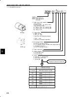
Page 217: ...ting a Servopack 212 5 1 3 Digital Operator 216 5 1 1 Selecting a Servomotor 1 The selection of an SGM or SGMP Servomotor matched to the servo system in which it is used is based on the servomotor typ...

Page 218: ...dard application U 200V L 100V U and L are UL Standard application 3 Encoder specification 3 2048 P R incremental encoder W 12 bit absolute encoder Available upon special request S 15 bit absolute enc...

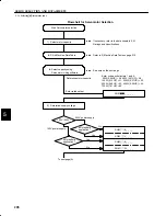
Page 219: ...P Servomotor is conducted according to the flowchart in the next page If an SGMP Servomotor is selected replace SGM with SGMP SGMP Servomotors are available from 100W 0 13HP to 750W 1 01HP A 1500W 2 0...

Page 220: ...page 210 D Select capacity using Servomotor sizing software See note on the next page Determine motor capacity Enter rated output 2 Determine supply voltage 100V 200V 200 V power supply 100 V power su...

Page 221: ...hout key Straight with key Under gravitational load Oil used at end of shaft Gravitational load oil Subject to water droplets With brake With shaft seal With brake and shaft seal Drip proofed End Serv...

Page 222: ...rew Vertical Axis Load mass W1 kg lb Counterweight W2 kg lb Coefficient of friction Motor Overall efficiency Gear coupling Gear ratio R Nm Nl Gear coupling GD2g Gear coupling GD2g kg cm2 lb in2 Ball s...

Page 223: ...b in2 Load torque T kg cm2 lb in2 T Overall efficiency Motor Gear ratio R Nm Nl Gear coupling GD2 Gear coupling GD2g kg cm2 lb in2 Gear coupling GD2g GD2 7 Others Load GD2 GD2 kg cm2 lb in2 Load torqu...

Page 224: ...selection of a DR2 Servopack matched to the servo system in which it is used is based on the Servopack type that is the four to six alphanumeric characters after DR2 described below The numbers 1 to 5...

Page 225: ...tion control 4 Factory setting of applicable motor type Blank SGM Servomotor P SGMP Servomotor Flowchart for Servopack selection Selected Servopack type D D D D D D Example Axis 1 Axis 2 D D D The app...

Page 226: ...l to the motor capacity Enter rated output Enter code as characters 1 and 2 30W 0 04HP A3 50W 0 07HP A5 100W 0 13HP 01 200W 0 27HP 02 300W 0 40HP 03 400W 0 53HP 04 750W 1 01HP 08 2 Determine supply vo...

Page 227: ...g a Series Servo 215 End Servopack selection DR2 jjjjj DR2 jjjjj F 5 Determine option specifications Semi closed specifications standard Full closed specifications Semi closed Full closed From the pre...

Page 228: ...ld in the hand while connected with the 1 m cable supplied Note Mount type digital operator JUSP OP03A cannot be used for DR2 Servopack Instead of digital operator also personal computer IBM PC can be...

Page 229: ...f SGM and SGMP Servomotors are shown below Refer to them as required when selecting a Servomotor 2 Ratings and Specifications of 200 VAC SGM Servomotors Time rating continuous Heat resistance class Cl...

Page 230: ...eleration 1 rad s2 45200 61200 79500 51800 666000 35600 Inertia Time Constant ms 1 5 0 9 0 5 0 4 0 3 0 3 Inductive Time Constant ms 1 5 1 8 1 9 5 4 6 4 13 1 These items and torque motor speed characte...

Page 231: ...cm Coil Resistance at 20 C Rated Current A at 20 C SGM A3jjjj 30 6 2 0 1350 0 067 SGM A5jjjj 50 6 2 0 1350 0 067 SGM 01jjjj 100 6 3 5 1350 0 067 SGM 02jjjj 200 6 5 15 1246 0 072 SGM 04jjjj 400 6 5 15...

Page 232: ...Motor Speed r min Motor Speed r min Motor Speed r min Motor Speed r min 4000 3000 2000 1000 0 0 0 1 0 2 0 3 0 4 0 20 40 60 4000 3000 2000 1000 0 0 0 15 0 3 0 45 0 6 0 20 40 60 80 100 4000 3000 2000 1...

Page 233: ...Max Rotation Speed 1 r min 4500 Torque Constant 1 N m A rms 0 392 0 349 0 535 0 641 q oz in A rms 55 5 49 4 75 8 91 0 Moment of Inertia Incremental encoder no h ldi b k GD2 M 4 kg m2 10 4 0 065 0 209...

Page 234: ...or Model Motor Capacity W Holding Brake Specifications Capacity W Holding Torque kg cm Coil Resistance at 20 C Rated Current A at 20 C SGMP 01jjjj 100 6 5 0 1555 0 062 SGMP 02jjjj 200 5 10 1573 0 056...

Page 235: ...08A V Motor Speed r min Motor Speed r min Motor Speed r min Motor Speed r min 4000 3000 2000 1000 0 0 0 2 0 4 0 6 0 8 0 40 80 120 4000 3000 2000 1000 0 0 0 5 1 1 5 2 0 100 200 300 4000 3000 2000 1000...

Page 236: ...2 q oz in 40 5 67 7 135 270 527 7 Rated Current 1 A rms 0 63 0 9 2 2 2 7 3 7 Instantaneous Peak Current 1 A rms 2 0 2 9 7 1 8 4 14 8 Rated Rotation Speed 1 r min 3000 Max Rotation Speed 1 r min 4500 T...

Page 237: ...e Holding Brake a SGM Type Rated Voltage 90 VDC Standard Motor Model Motor Capacity W Holding Brake Specifications Capacity W Holding Torque kg cm Coil Resistance at 20 C Rated Current A at 20 C SGM A...

Page 238: ...3B W Motor Speed r min Motor Speed r min Motor Speed r min Motor Speed r min TORQUE N m 4000 3000 2000 1000 0 0 0 1 0 2 0 3 0 4 0 20 40 60 4000 3000 2000 1000 0 0 0 15 0 3 0 45 0 6 0 20 40 60 80 100 4...

Page 239: ...Constant 1 N m A rms 0 160 0 258 0 246 q oz in A rms 22 8 36 5 34 9 Moment of Inertia Incremental encoder no holding brake GD 2 M 4 kg m2 10 4 0 065 0 209 0 347 g oz in s2 10 3 0 917 2 96 4 92 Increm...

Page 240: ...MP 01jjjj 100 6 5 0 1555 0 062 SGMP 02jjjj 200 5 10 1573 0 056 SGMP 04jjjj 400 7 6 20 1062 0 085 SGMP 08jjjj 750 7 5 37 1083 0 083 SGMP 15jjjj 1500 10 73 832 0 11 b SGMP Type Rated Voltage 24 VDC Semi...

Page 241: ...SGMP 01B W SGMP 02B W SGMP 03B W Motor Speed r min Motor Speed r min Motor Speed r min 4000 3000 2000 1000 0 0 0 2 0 4 0 6 0 8 0 50 100 4000 3000 2000 1000 0 0 0 5 1 1 5 2 0 100 200 300 4000 3000 200...

Page 242: ...l Load Fr N lb Allowable Thrust Load Fs N lb LR mm in Reference Diagram SGM A3 68 15 54 12 20 0 82 SGM A5 68 15 54 12 20 0 82 SGM 01 78 17 54 12 20 0 82 SGM 02 245 55 74 16 25 1 02 LR SGM 03 245 55 74...

Page 243: ...e load 4 Impact Resistance Mount the servomotor with the axis horizontal The servomotor must withstand the following ver tical impacts Impact Acceleration 98 m s2 10 G Number of Impacts 2 NOTE In SGM...

Page 244: ...M and SGMP Servomotors meet the following vibration class at rated speed Vibration Class 15 m or below TERMS Vibration Class Vibration class 15 m or below indicates that the total amplitude of vibrati...

Page 245: ...A3BC A5BC 01BC 02BC 03BC Max Applicable Motor Capacity W HP 30 0 04 50 0 07 100 0 13 200 0 27 400 0 53 750 1 01 30 0 04 50 0 07 100 0 13 200 0 27 300 0 40 Combined S ifi Motor Type A3Aj A5Aj 01Aj 02A...

Page 246: ...r ence Voltage 6 VDC positive motor rotation with positive reference at rated speed factory setting Variable setting range 2 to 10 VDC at rated torque ence Input Impedance Approx 30k Circuit Time Cons...

Page 247: ...5 Load Inertia 2 Supply voltage should not exceed 230 V 10 253 V or 115 V 10 127 V A step down transformer is required if the voltage should exceed these values 3 Use within the ambient temperature r...

Page 248: ...ingle phase full wave rectification IGBT PWM sine wave driven Feedback Incremental encoder 2048 P R absolute encoder 1024 P R Loca i Ambient Temp 0 to 55 C 3 tion Storage Temp 20 C to 85 C Ambient Sto...

Page 249: ...applicable to 100V 200W 300W or 200V 400W 750W Values are when motor speed is 3000r min max If load inertias exceed these ranges restrict the operation or use a regenerative unit appli cable to 200V 3...

Page 250: ...j 200W 0 27HP 2 0 14 5 27 5 04Aj 400W 0 53HP 2 6 22 2 6 41 2 08Aj 750W 1 01HP 4 4 36 1 6 13 55 1 Supply Voltage 100V A3Bj 30W 0 04HP 0 63 2 9 15 9 A5Bj 50W 0 07HP 0 90 4 4 17 4 01Bj 100W 0 13HP 2 2 12...

Page 251: ...erefore the Servopack allowable power is limited by the overload protective function as shown below The overload detection level is quoted under hot start conditions at a motor ambient temper ature of...

Page 252: ...NR JM JL Kt IR ms ms NR Motor rated speed r min JM Motor moment of inertia kg m2 lb in s2 GD2 M 4 JL Load converted to shaft moment of inertia kg m2 GD2 L 4 Kt Motor torque constant N m A lb in A IR M...

Page 253: ...he load inertia becomes the worse the movement response of the load The size of the load inertia JL allowable when using a Servomotor depends on the motor capacity as shown in the diagrams below Small...

Page 254: ...3 kg m2 10 4 oz in s2 10 3 kg m2 10 4 oz in s2 10 3 kg m2 10 4 oz in s2 10 3 0 63 8 92 40 1 11 0 5 73 81 1 17 0 63 7 51 2 284 6 2 83 4 50 20 1 400W 0 53HP 3000 4500 r min 0 Note 1 The above diagrams r...

Page 255: ...z in s2 10 3 kg m2 10 4 oz in s2 10 3 kg m2 10 4 oz in s2 10 3 0 63 8 21 11 0 17 0 3 69 52 3 0 0 0 0 5 73 81 1 3000 3000 4500 4500 Note 1 The above diagrams represent deceleration under maximum torque...

Page 256: ...kg m2 10 4 oz in s2 10 3 27 6 10 41 147 4 6 27 88 8 2 65 37 5 18 5 262 0 2 95 41 8 1 95 0 0 3000 4500 0 0 3000 4500 0 0 3000 4500 Note 1 Diagrams above represent deceleration under maximum torque App...

Page 257: ...n s2 10 3 27 6 6 27 88 8 1 95 10 41 147 4 0 0 3000 4500 0 0 3000 4500 Note 1 Diagrams above represent deceleration under maximum torque Applying an acceleration deceleration curve to the reference all...

Page 258: ...g load that is a load which tends to continually rotate the motor Under an overhanging load e g when the direction of the torque applied by the motor is opposite from the direction of shaft rotation t...

Page 259: ...our categories a Incremental encoder no brake from page 248 b Incremental encoder with brake from page 253 c Absolute encoder no brake from page 258 d Absolute encoder with brake from page 264 Motor c...

Page 260: ...1 40 1 57 U W T Screw Type SGM L LL LM S QK U W T Screw dimen sions Out put W HP Approx mass kg lb Allow able radial load N lb Allow able thrust load N lb A3A312 94 5 3 2 69 5 2 36 5 1 6 0 2 No key 30...

Page 261: ...es with JIS B 1301 1976 precision A straight key is supplied 4 The quoted allowable radial load is the value at a position 20 mm 0 79 in from the mo tor mounting surface 200 W 0 27 HP 300 W 0 40 HP 40...

Page 262: ...0 0 0 1 7 3 03B314 6 08 4 90 3 56 20 0 9 3 0 12 5 0 20 5 0 20 0 40 3 75 03B316 0 79 0 12 0 20 0 20 M5 depth 8 0 31 04A312 154 5 6 08 124 5 90 90 5 3 6 No key 400 0 3 1 7 3 04A314 6 08 4 90 3 56 20 0 9...

Page 263: ...ions Output W HP Approx mass kg lb Allowable radial load N lb Allowable thrust load N lb 08A312 No key 750 1 01 3 4 0 392 88 1 147 33 0 08A314 30 1 18 3 0 12 5 0 20 5 0 20 1 01 7 50 08A316 1 18 0 12 0...

Page 264: ...g 172169 1 Made by AMP Pin 170359 1 or 170363 1 Plug 172167 1 AMP Connected to Cap 172161 1 Socket 170361 1 or 170365 1 Motor Plug Encoder Plug Socket 170362 1 or 170366 1 Cap 172159 1 Connected to C...

Page 265: ...04 A A Screw U W T Type SGM L LL LM LB S QK U W T Screw dimen sions Out put W HP Approx mass kg lb Allow able radial load N lb Allow able thrust load N lb A3A312B 126 0 4 96 101 0 3 98 36 5 1 44 31 5...

Page 266: ...value at a position 20 mm 0 79 in from the mo tor mounting surface 5 The electromagnetic brake is only to hold the load in position and cannot be used to stop the motor 200 W 0 53 HP 300 W 0 40 HP 40...

Page 267: ...0 5 0 20 0 40 4 85 03B316B 0 79 0 12 0 20 0 20 M5 depth 8 0 31 04A312B No key 400 0 3 04A314B 20 0 9 3 0 12 5 0 20 5 0 20 0 53 04A316B 0 79 0 12 0 20 0 20 M5 depth 8 0 31 Note 1 The detector uses an i...

Page 268: ...ly 80 3 15 4 R8 2 90 3 54 Type SGM QK U W T Screw dimen sions Output W HP Approx mass kg lb Allowable radial load N lb Allowable thrust load N lb 08A312B No key 750 4 3 392 88 1 147 33 0 08A314B 30 3...

Page 269: ...72160 1 Encoder Plug Incremental Encoder Wiring Specifications A channel output Blue A channel output Blue Black B channel output Yellow B channel output Yellow Black Green Green Black Gray Red FG Fra...

Page 270: ...0 37 4 R3 7 Y Y QK U T W Screw Type SGM L LL LM S QK U W T Screw dimen sions Out put W HP Approx mass kg lb Allow able radial load N lb Allow able thrust load N lb A3AW12 117 5 63 92 5 3 6 36 5 1 6 0...

Page 271: ...ification and type B indicates 100 V specification 3 A3A B W14 A3A B W16 A5A B W14 A5A B W16 01A B W14 and 01A B W16 have a keyed shaft The keyway complies with JIS B 1301 1976 preci sion A straight k...

Page 272: ...8 0 02 7 5 0 30 3 0 12 30 1 18 4 R5 3 50 0 0 025 1 97 0 0010 0 QK Y Y 70 2 76 U T W Screw Type SGM L LL LM QK U W T Screw dimen sions Out put W HP Approx mass kg lb Allow able radial load N lb Allow a...

Page 273: ...V specification and type B indicates 100 V specification 3 02A B W14 02A B W16 03BW14 03BW16 04AW14 and 04AW16 have a keyed shaft The keyway complies with JIS B 1301 1976 precision A straight key is s...

Page 274: ...4 0 QK Y Y 90 3 54 0 79 70 0 0 030 2 76 0 0012 0 35 1 38 206 8 10 166 6 54 111 4 35 40 1 57 U T W Screw Type SGM QK U W T Screw dimen sions Output W HP Approx mass kg lb Allowable radial load N lb All...

Page 275: ...d to Connected to Cap 172163 1 Socket 170361 1 or 170365 1 Terminal to discharge capacitor for product dispatch Do not use A channel output Blue A channel output White Blue B channel output Yellow B c...

Page 276: ...0 0008 0 02 4 0 16 5 0 20 9 5 0 37 4 R3 7 Y Y QK 4 0 16 25 0 98 2 5 0 10 LB U T W Screw Type SGM L LL LM LB S QK U W T Screw dimen sions Out put W HP Approx mass kg lb Allow able radial load N lb All...

Page 277: ...osition and cannot be used to stop the motor 200 W 0 27 HP 300 W 0 40 HP 400 W 0 53 HP Absolute encoder 1024 P R Motor Lead Teflon wire AWG22 UL1828 or UL3534 Protective Tube Black Cross section Y Y M...

Page 278: ...56 20 0 79 3 0 12 5 0 20 5 0 20 0 40 5 07 03BW16B 0 79 0 12 0 20 0 20 5 0 20 M5 depth 8 0 31 04AW12B No key 400 0 3 04AW14B 20 0 9 3 0 12 5 0 20 5 0 20 0 53 04AW16B 0 79 0 12 0 20 0 20 M5 depth 8 0 31...

Page 279: ...0 35 1 38 A A 3 0 12 40 1 57 16 0 0 011 44 5 1 75 2 8 0 11 Brake Lead 250 5 9 86 210 5 8 29 111 4 35 U T W Screw Type SGM QK U W T Screw dimen sions lb Output W HP Approx mass kg lb Allow able radial...

Page 280: ...ecifications Incremental Encoder Wiring Specifications Terminal to discharge capacitor for product dispatch Do not use A channel output Blue A channel output White Blue B channel output Yellow B chann...

Page 281: ...ith brake from page 284 Motor capacities are available as 100 W 0 13 HP 200 W 0 27 HP 300 W 0 40 HP 400 W 0 53 HP 750 W 1 01 HP These are grouped into three categories as follows 100W 0 13 HP 200W 0 2...

Page 282: ...alant Hex Nut 14 0 55 4 5 5 4 0 22 MTG Holes Shaft end screw hole SGMP 01A B 316 with key type only Type SGMP L LL LM S QK U W T Screw dimen sions Out put W HP Approx mass kg lb Al low able radial loa...

Page 283: ...ght key is supplied 4 The quoted allowable radial load is the value at a position 20 mm 0 79 in from the mo tor mounting surface 5 Conforms to IP55 protective structure except connector and output sha...

Page 284: ...3 23 2 68 16 0 63 3 0 12 5 0 20 5 0 20 0 40 4 63 03B316 0 63 0 12 0 20 0 20 M5 depth 8 0 31 04A312 No key 400 0 3 04A314 16 0 63 3 0 12 5 0 20 5 0 20 0 53 04A316 0 63 0 12 0 20 0 20 M5 depth 8 0 31 N...

Page 285: ...e thrust load N lb 08A312 No key 750 4 2 392 88 1 147 33 0 08A314 22 3 5 5 1 01 9 26 08A316 0 87 0 12 0 20 0 20 M5 depth 8 0 31 Note 1 The detector uses an incremental encoder 2048 P R 2 Type A indica...

Page 286: ...pecifications Encoder Plug Incremental Encoder Wiring Specifications Blue Blue Black Yellow Yellow Black Green Green Black Gray Red Orange Plug 172169 1 AMP Pin 170359 1 or 170363 1 Plug 172167 1 AMP...

Page 287: ...LB S QK U W T Screw dimen sions Out put W HP Approx mass kg lb Al low able radial load N lb Al low able thrus t load N lb 01A312B 111 4 37 86 3 39 42 5 1 67 29 1 14 8 0 31 No key 100 0 13 0 9 1 98 78...

Page 288: ...d cannot be used to stop the motor 6 Conforms to IP55 protective structure except connector and output shaft faces 200 W 0 27HP 300W 0 40 HP 400 W 0 53HP Encoder Lead Encoder Plug Motor Plug Sealant I...

Page 289: ...2 0 20 0 20 M5 depth 8 0 31 04A312B No key 400 0 3 04A314B 16 0 63 3 0 12 5 0 20 5 0 20 0 53 04A316B 0 63 0 12 0 20 0 20 M5 depth 8 0 31 Note 1 The detector uses an incremental encoder 2048 P R 2 Type...

Page 290: ...w Shaft end screw hole SGMP 08A316B with key type only Type SGMP QK U W T Screw dimen sions Output W HP Approx mass kg lb Allowable radial load N lb Allowable thrust load N lb 08A312B No key 750 1 01...

Page 291: ...r 170366 1 Pin 170360 1 or 170364 1 Cap 172160 1 Motor Wiring Specifications Incremental Encoder Wiring Specifications Plug 172169 1 AMP Pin 170359 1 or 170366 1 Plug 172168 1 AMP Connected to Connect...

Page 292: ...N lb 01AW12 122 5 82 97 5 3 8 42 5 1 6 8 0 31 No key 100 0 13 0 9 1 98 78 1 49 11 0 01BW12 4 82 3 84 1 67 0 31 y 0 13 1 98 17 5 11 0 01AW14 14 0 1 8 0 0 3 0 12 3 0 12 01BW14 0 55 0 07 0 12 0 12 01AW1...

Page 293: ...16 5 9 86 5 3 1 48 1 1 89 No key 200 0 2 1 6 3 3 245 55 1 68 15 3 02BW12 4 59 3 41 1 89 y 0 27 3 53 02AW14 16 0 63 3 0 12 5 0 20 5 0 20 02BW14 0 63 0 12 0 20 0 20 02AW16 M5 depth 8 02BW16 depth 8 0 31...

Page 294: ...or Plug Cross section Y Y Hex nut 17 0 67 Motor Lead UL2464 Sealant 0 04 4 10 4 0 39 MTG Hoses UL20276 35 1 38 300 30 12 0 47 10 5 0 41 146 5 75 106 4 17 66 7 2 63 10 0 39 3 5 0 14 40 1 57 0 02 0 0008...

Page 295: ...64 1 Cap 172159 1 Motor Wiring Specifications Absolute Encoder Wiring Specifications Plug 172171 1 AMP Pin 170359 1 or 170363 1 Plug 172167 1 AMP Connected to Connected to Cap 172163 1 Socket 170361 1...

Page 296: ...que Screw Cross section Y Y Hex nut 14 0 55 4 5 5 4 0 22 MTG Holes 55 2 17 Shaft end screw hole SGMP 01A B W16B with key type only Type SGMP L LL LM LB S QK U W T Screw dimen sions Out put W HP Approx...

Page 297: ...B W16B have a keyed shaft The keyway complies with JIS B 1301 1976 precision A straight key is supplied 4 The quoted allowable radial load is the value at a position 20 mm 0 79 in from the mo tor moun...

Page 298: ...W16B with key type only j80 3 15 21 0 83 18 0 71 MAX U W T 90 3 54 Sealant 35 1 38 300 30 11 81 1 18 0 0 0004 0 55 2 76 0 0 0012 Type SGMP L LL LM QK U W T Screw dimen sions Output W HP Approx mass k...

Page 299: ...coder 1024P R Holding Brake deenergization operation Voltage 90 VDC Brake holding torque motor rated torque Cross section Y Y Hex nut 17 0 67 12 0 47 10 5 0 41 j 120 4 72 38 1 50 28 1 10 MAX U W T 4 1...

Page 300: ...utput White Blue B channel output Yellow B channel output White Yellow Green White Green Black Red FG Frame Ground Green Yellow Z channel output Z channel output 0 V power supply 5 V power supply 1 2...

Page 301: ...as 30 W 0 04 HP 50 W 0 07 HP 100 W 0 13 HP 200 W 0 27 HP 300 W 0 40 HP 400 W 0 53 HP 750 W 1 01 HP These are grouped into three categories as follows 30W 0 04 HP 50W 0 07 HP 100W 0 13 HP 200W 0 27 HP...

Page 302: ...rew Type SGM L LL LM S QK U W T Screw dimen sions Out put W HP Approx mass kg lb Allow able radial load N lb Allow able thrust load N lb A3V312 94 5 3 2 69 5 2 36 5 1 6 0 2 No key 30 0 0 0 3 0 66 68 1...

Page 303: ...1 34 0 83 11 81 1 18 1 38 0 12 1 18 11 81 1 18 50 0 0 025 1 97 0 0010 0 0 28 0 24 2 76 2 36 0 55 0 47 Shaft end screw hole SGM jjV W 316 with key type only Marked Wire Sealant 14 0 0 011 0 55 0 0004...

Page 304: ...UL2854 Incremental Encoder 2048 P R Cross section Y Y 1 34 4 7 0 28 MTG Holes Motor Lead 7 0 29 Sealant 0 0016 0 0008 7 28 1 38 11 81 1 18 1 38 0 12 1 57 11 81 1 18 16 0 0 011 0 63 0 0004 0 0 31 0 31...

Page 305: ...50 or 100 W only Motor Wiring Specifications Incremental Encoder Wiring Specifications Blue Blue Black Yellow Yellow Black Green Green Black Gray Red Orange Plug 172169 1 Made by AMP Pin 170359 1 or...

Page 306: ...37 0 67 Sealant Screw 2 Screw Type SGM L LL LM LB S QK U W T Screw dimen sions Out put W HP Approx mass kg lb Allow able radial load N lb Allow able thrust load N lb A3V312B 126 0 4 96 101 0 3 98 36...

Page 307: ...5 The electromagnetic brake is only to hold the load in position and cannot be used to stop the motor 200 W 0 53 HP 300 W 0 40 HP 400 W 0 27 HP Encoder Lead UL2854 Incremental Encoder 2048 P R Cross...

Page 308: ...6 20 0 9 3 0 12 5 0 20 5 0 20 0 40 4 85 03W316B 0 79 0 12 0 20 0 20 M5 depth 8 0 31 04V312B No key 400 0 3 04V314B 20 0 9 3 0 12 5 0 20 5 0 20 0 53 04V316B 0 79 0 12 0 20 0 20 M5 depth 8 0 31 Note 1 T...

Page 309: ...ole SGM 08V316B with key type only Screw Type SGM QK U W T Screw dimen sions Output W HP Approx mass kg lb Allowable radial load N lb Allowable thrust load N lb 08V312B No key 750 1 01 4 3 9 8 392 88...

Page 310: ...ifications Blue Blue Black Yellow Yellow Black Green Green Black Gray Red Orange Plug 172169 1 AMP Pin 170359 1 or 170363 1 Plug 172168 1 AMP Connected to Connected to Cap 172161 1 Socket 170361 1 or...

Page 311: ...ut put W HP Approx mass kg lb Allow able radial load N lb Allow able thrust load N lb A3VW12 117 5 4 63 92 5 3 64 36 5 1 44 6 0 24 No key 30 0 04 0 45 0 99 68 15 3 54 12 1 A3WW12 117 5 4 63 92 5 3 64...

Page 312: ...ble radial load is the value at a position 20 mm 0 79 in from the mo tor mounting surface 200 W 0 27 HP 300W 0 40 HP 400 W 0 53 HP Encoder Lead UL20276 Cross section Y Y 7 0 28 Motor Lead f7 f0 29 55...

Page 313: ...00 0 0 1 8 3 9 03WW14 6 91 5 73 3 56 20 0 9 3 0 12 5 0 20 5 0 20 0 40 3 97 03WW16 0 79 0 12 0 20 0 20 M5 depth 8 0 31 04VW12 No key 400 1 04VW14 20 0 9 3 0 12 5 0 20 5 0 20 15 7 04VW16 0 79 0 12 0 20...

Page 314: ...81 1 18 4 R8 2 QK Y Y A A f0 04 A Screw Shaft end screw hole SGM 08VW16 with key type only Type SGM QK U W T Screw dimen sions Output W HP Approx mass kg lb Allowable radial load N lb Allowable thrus...

Page 315: ...Plug 172171 1 AMP Pin 170359 1 or 170363 1 Plug 172167 1 AMP Connected to Connected to Cap 172163 1 Socket 170361 1 or 170365 1 Purple Gray White Gray White Orange Orange White Purple Terminal to dis...

Page 316: ...ype SGM L LL LM LB S QK U W T Screw dimen sions Out put W HP Appr ox mass kg lb Al low able radial load N lb Al low able thrust load N lb A3VW12B 149 0 5 87 124 0 4 88 36 5 1 44 31 5 1 24 6 0 24 No ke...

Page 317: ...position and cannot be used to stop the motor 200 W 0 27 HP 300 W 0 40 HP 400 W 0 53 HP Encoder Lead UL20276 Absolute Encoder 1024 P R Cross section Y Y 4 f5 5 f0 22 MTG Holes Motor Lead f7 f0 29 Sea...

Page 318: ...3 56 20 0 9 3 0 12 5 0 20 5 0 20 0 40 5 07 03WW16B 0 79 0 12 0 20 0 20 M5 depth 8 0 31 04VW12B No key 400 0 3 04VW14B 20 0 9 3 0 12 5 0 20 5 0 20 0 53 04VW16B 0 79 0 12 0 20 0 20 M5 depth 8 0 31 Note...

Page 319: ...300 30 11 81 1 18 35 1 38 U W T A A A 300 30 11 81 1 18 Y Y 35 1 38 QK Screw 4 R8 2 Type SGM QK U W T Screw dimen sions lb Output W HP Approx mass kg lb Allowable radial load N lb Allowable thrust lo...

Page 320: ...ecifications Incremental Encoder Wiring Specifications Terminal to discharge capacitor for product dispatch Do not use Blue White Blue Yellow White Yellow Green White Green Black Red Green Yellow Purp...

Page 321: ...0 W 0 27 HP 300 W 0 40 HP 400 W 0 53 HP 750 W 1 01 HP These are grouped into three categories as follows 100W 0 13 HP 200W 0 27 HP 300W 0 40 HP 400W 0 53 HP 750W 1 01 HP As for the dimensional drawing...

Page 322: ...le SGMP 01V W 316 with key type only Type SGMP QK U W T Screw dimensions Output W HP Approx mass kg lb Allowable radial load N lb Allowable thrust load N lb 01V312 No key 100 0 13 0 7 1 54 78 17 5 49...

Page 323: ...type only Type SGMP L ML1 ML2 QK U W T Screw dimen sions Output W HP Approx mass kg lb Allowable radial load N lb Allowable thrust load N lb 02V312 92 62 48 1 No key 200 1 4 245 55 1 68 15 3 02W312 3...

Page 324: ...ameplate 16 0 0 011 0 63 0 0004 0 0 0016 Encoder Lead UL2854 6 0 24 1 38 1 57 1 50 0 41 Screw Hex Nut 14 0 55 5 71 2 63 0 75 4 78 Shaft end screw hole SGMP 08V316 with key type only Type SGMP QK U W T...

Page 325: ...ing Specifications Plug 172169 1 AMP Pin 170359 1 or 170363 1 Plug 172167 1 AMP Connected to Connected to Cap 172161 1 Socket 170361 1 or 170365 1 Blue Blue Black Yellow Yellow Black Green Green Black...

Page 326: ...0VDC C 24VDC Brake Holding Torque Motor Rated Torque 4 37 3 39 8 0 009 0 31 0 0004 0 0 0 55 Shaft end screw hole SGMP 01V W 316B C with key type only Type SGMP QK U W T Screw dimensions Output W HP Ap...

Page 327: ...P 400 W 0 53HP Motor Lead UL2464 7 0 29 Encoder Lead UL2854 6 0 24 Incremental Encoder 2048 P R Cross section Y Y Marked Wire 1 18 4 7 0 28 MTG Holes Sealant 0 0016 0 0008 1 24 11 81 1 18 1 38 0 83 11...

Page 328: ...3 0 12 5 0 20 5 0 20 0 40 03W316B C 0 63 0 12 0 20 0 20 M5 depth 8 04V312B C No key 400 0 3 04V314B C 16 0 63 3 0 12 5 0 20 5 0 20 0 53 04V316B C 0 63 0 12 0 20 0 20 M5 depth 8 Note 1 The detector us...

Page 329: ...key type only Type SGMP QK U W T Screw dimens ions Output W HP Approx mass kg lb Allowable radial load N lb Allowable thrust load N lb 08V312B C No key 750 1 01 5 7 12 57 392 88 1 147 33 0 08V314B C...

Page 330: ...cifications Plug 172169 1 AMP Pin 170359 1 or 170363 1 Plug 172168 1 AMP Connected to Connected to Cap 172161 1 Socket 170361 1 or 170365 1 Motor Wiring Specifications A channel output Blue A channel...

Page 331: ...W W16 with key type only Type SGMP QK U W T Screw dimensions Out put W HP Approx mass kg lb Allowable radial load N lb Allowable thrust load N lb 01VW12 No key 100 0 13 0 95 2 09 78 17 5 49 11 0 01WW1...

Page 332: ...MP L LL LM QK U W T Screw dimen sions Out put W HP Approx mass kg lb Allowable radial load N lb Allowable thrust load N lb 02VW12 116 5 9 86 5 3 1 48 1 1 89 No key 200 0 2 1 6 3 3 245 55 1 68 15 3 02W...

Page 333: ...have a keyed shaft The keyway complies with JIS B 1301 1976 precision A straight key is supplied 4 The quoted allowable radial load is the value at a position 25 mm 0 98 in from the mo tor mounting s...

Page 334: ...08VW16 with key type only Type SGMP QK U W T Screw dimen sions Output W HP Approx mass kg lb Allowable radial load N lb Allowable thrust load N lb 08VW12 No key 750 4 7 392 88 1 147 33 0 08VW14 22 3 5...

Page 335: ...reen Black Red FG Frame Ground Green Yellow Plug 172171 1 AMP Pin 170359 1 or 170363 1 Plug 172167 1 AMP Connected to Connected to Cap 172163 1 Socket 170361 1 or 170365 1 1 2 3 4 5 6 7 8 13 14 15 S c...

Page 336: ...t symbol of motor type B 90VDC C 24VDC Brake Holding Torque Motor Rated Torque 126 5 4 98 151 5 5 96 8 0 009 0 31 0 0004 0 0 0 55 Sealant 1 67 Nameplate Shaft end screw hole SGMP 01V W W16B C with key...

Page 337: ...l load is the value at a position 20 mm 0 79 in from the mo tor mounting surface 5 The electromagnetic brake is only to hold the load in position and cannot be used to stop the motor 6 Conforms to IP5...

Page 338: ...Motor Rated Torque 14 0 011 0 55 0 0004 0 0 0 55 3 54 Nameplate Shaft end screw holeSGMP jjV W W16B C with key type only Type SGMP L LL LM QK U W T Screw dimen sions Out put W HP Approx mass kg lb All...

Page 339: ...1024 P R Cross section Y Y 4 10 0 39 MTG Holes Motor Lead UL2464 7 0 29 Sealant 0 0016 0 0008 11 81 1 18 1 38 0 14 11 81 1 18 110 0 0 035 4 33 0 0014 0 4 72 0 39 Marked Wire Name plate 16 0 0 011 0 6...

Page 340: ...output White Blue B channel output Yellow B channel output White Yellow Green White Green Black Red FG Frame Ground Green Yellow Z channel output Z channel output 0 V power supply 5 V power supply 1...

Page 341: ...27HP Types DR2 A3Aj to 02Aj 100V 30W 0 04 HP to 100 W 0 13HP Types DR2 A3Bj to 01Bj b Semi closed loop standard 200V 400W 0 53 HP 750W 1 01 HP Types DR2 04Aj 08Aj 100V 200W 0 27 HP 300W 0 40 HP Types...

Page 342: ...0 04 HP to 200 W 0 27HP DR2 A3Bj to 01Bj 100V 30W 0 04 HP to 100 W 0 13HP Approx Mass 2 5 kg 5 51 lb 9 25 Heat Sink 1 18 1 18 0 30 9 84 0 30 0 59 0 59 0 59 0 59 0 59 8 66 0 59 7 91 0 09 1 30 0 24 1 1...

Page 343: ...750W 1 01 HP DR2 02Bj 03Bj 100V 200W 0 27 HP 300W 0 40 HP Approx Mass 3 7 kg 8 16 lb 9 25 Heat Sink 0 30 9 84 External Terminals 11P FRONT2 5H SA5 PHOENIX CONTACT VOLTAGE INDICATION 9 25 0 30 0 30 0...

Page 344: ...es DR2 A3Aj F to 02Aj F 100V 30W 0 04 HP to 100W 0 13 HP Types DR2 A3Bj F to 01Bj F Approx Mass 2 5 kg 5 51 lb 9 25 Heat Sink 1 18 1 18 0 30 9 84 0 30 0 59 0 59 0 59 0 59 0 59 8 66 0 59 7 91 0 09 1 30...

Page 345: ...F to 08Aj F 100V 200W 0 27 HP to 300W 0 40 HP Types DR2 02Bj F to 03Bj F Approx Mass 3 7 kg 8 16 lb 9 25 Heat Sink 0 30 9 84 External Terminals 11P FRONT2 5H SA5 PHOENIX CONTACT VOLTAGE INDICATION 9...

Page 346: ...gital Operator Dimensional Drawing a JUSP OP02A 1 Hand held type TYPE 17JE 23090 02 Made by DAIICHI DENSHI KOGYO K K Approx Mass 0 18 kg 0 40 lb 2 0 18 MTG HOLES 4 92 2 48 1 97 5 31 0 31 39 37 0 73 0...

Page 347: ...e also included 5 5 1 Selecting Peripheral Devices 335 5 5 2 Order List 341 5 5 1 Selecting Peripheral Devices Select the peripheral devices using the flowcharts on the subsequent pages The items belo...

Page 348: ...olute encoder Incremental Absolute Incremental Absolute Select connector kit Select connector kit Select connector kit Select connector kit DP9420009 3 DP9420009 2 DP9420009 4 1 Select brake power sup...

Page 349: ...previously selected at step 1 Yes No Select connector kit to b Connector both ends Servopack end without connector Cable only DP9320082 2 DP9320082 3 DP9320082 4 DP9320082 5 DP9320086 1 DP9320086 2 DP...

Page 350: ...y selected at step 1 Yes No Select connector kit 2 Select battery for absolute encoder ER6VC3 3 6V to c Connector both ends Servopack end without connector Cable only DP9320084 1 DP9320084 2 DP9320084...

Page 351: ...acity Noise filter Noise filter Noise filter Noise filter from c Servopack power supply 200 V 100 V 200 V 100 V Servopack capacity Servopack capacity 30 to 200W 400W 750W 30 to 100W 200W 300W Noise fi...

Page 352: ...heral device selection Application I to IV Investigate regenerative unit capacity using AC Servomotor sizing software Result of investigation into regenerative unit Applicable No regenerative unit req...

Page 353: ...ripheral devices SGM Servomotor Servomotor Type Qty SGM jjjjjjj SGM jjjjjjj SGM jjjjjjj SGM jjjjjjj SGM jjjjjjj SGM jjjjjjj DR2 Servopack excluding cables and connectors Servopack Type Qty DR2 jjjj j...

Page 354: ...ervomotor without Brake Cable Only 1 Purchase Separately Cable Type Qty DP8409359 1 3 m 9 8 ft DP8409359 2 5 m 16 4 ft DP8409359 3 10 m 32 8 ft DP8409359 4 15 m 49 2 ft DP8409359 5 20 m 65 6 ft 1 Cust...

Page 355: ...ke DP9420009 2 Incremental encoder with brake DP9420009 3 Absolute encoder no brake DP9420009 4 Absolute encoder with brake The three products in the diagrams below are supplied as a set 1 Encoder Con...

Page 356: ...Separately Cable Type Qty DP9320082 1 3m 9 8 ft DP9320082 2 5m 16 4 ft DP9320082 3 10m 32 8 ft DP9320082 4 15m 49 2 ft DP9320082 5 20m 65 6 ft E2 Cables for Incremental Encoder Servopack end without c...

Page 357: ...4 ft B9400064 3 10m 32 8 ft B9400064 4 15m 49 2 ft B9400064 5 20m 65 6 ft 3 Customer to attach connector to both ends of cable Requires K1 connector kit E4 Cables for Absolute Encoder Connector Both E...

Page 358: ...0085 5 20m 65 6 ft 2 Customer to attach connector to Servopack end of cable Requires K1 connector kit E6 Cables for Absolute Encoder Cable Only 3 Purchase Separately Cable Type Qty DP8409123 1 3m 9 8...

Page 359: ...arately Noise Filter Type Qty LF 205A 5A LF 210 10A LF 220 20A Magnetic Contactor Purchase Separately Magnetic Contactor Type Qty HI 15E5 30A Surge Suppressor Purchase Separately Surge Suppressor Type...

Page 360: ...for Speed Setting Purchase Separately Variable Resistor Type Qty 25HP 10B Cables for Connecting PC and Servopack Purchase Separately Cable Type Qty DE9405258 2m 6 6 ft Encoder Signal Converter Unit P...

Page 361: ...r Cables 355 5 6 3 Connector Kits 358 5 6 4 Brake Power Supply 363 5 6 5 Encoder Cables 365 5 6 6 Battery for Absolute Encoder 371 5 6 7 1CN Connector 371 5 6 8 Circuit Breaker 373 5 6 9 Noise Filter...

Page 362: ...5A j SGM A5V j 0 3 Class 5 A above 100 W 0 13HP 01AC SGM 01A j SGM 01V j 0 5 01ACP SGMP 01A j SGMP 01V j 200 W 0 27HP 02AC SGM 02A j SGM 02V j 0 75 02ACP SGMP 02A j SGMP 02V j 400 W 0 53HP 04AC SGM 04...

Page 363: ...j SGMP 02W j Class 10 A 300 W 0 40HP 03BC SGM 03B j SGM 03W j 1 4 15 LF 220 Single phase 200 VAC Class 20 A 03BCP SGMP 03B j SGMP 03W j Class 20 A Note For power ON OFF switch use contactor 30A or ab...

Page 364: ...s are used use the same size cable as those of L1 L2 Tightening torque is the same as those of L1 L2 0 5N m 2 The cable specifications were selected under conditions of three cables per bundle at 40_C...

Page 365: ...applied only when SGMP motor is used Cable Specifications When motor conforms to Japanese Standard When Yaskawa cables are used contact your Yaskawa representative for details When selecting non Yask...

Page 366: ...le Use twisted pair cable or twisted pair shielded cable Max wiring length is 3m 9 8ft Finished Cable Dimensions 16 0 mm 0 63 in MAX PG Signal Connector 2CN Cable Use Yaskawa cable Use twisted pair sh...

Page 367: ...ector for Motor End of Cable Cap 172159 1 4 pin Socket 170362 1 or 170366 1 Heat Shrink Tube Finished Dimension 7 5mm Max Cable AWG20 x 4 core Heat Shrink Tube 1 38 1 97 Spare Solder 35 L 50 9 0 35 b...

Page 368: ...e Type L in mm feet DP8409359 1 3000 100 0 10 0 33 0 DP8409359 2 5000 100 0 16 7 0 33 0 DP8409359 3 10000 500 0 33 3 1 67 0 DP8409359 4 15000 500 0 50 1 67 0 DP8409359 5 20000 500 0 66 7 1 67 0 AMP Co...

Page 369: ...409360 3 10000 500 0 33 3 1 67 0 DP8409360 4 15000 500 0 50 1 67 0 DP8409360 5 20000 500 0 66 7 1 67 0 AMP Connector Cap 172160 1 Socket 170362 1 or 170366 1 Manufactured by AMP Pin Red White Blue Gre...

Page 370: ...r types of connector kit are available according to the following information Is the encoder incremental or absolute Is the motor with or without a brake A connector kit is required in the following c...

Page 371: ...70365 1 0 17 0 88 0 93 14 0 0 55 4 2 0 17 16 0 63 3 Select one of the following two types of motor cable connector a Motor Without Brake Cap 172159 1 Socket 170362 1 or 170366 1 0 39 0 16 0 93 4 14 0...

Page 372: ...ately and use MRP Fjtype contact Connector Soldering type D A B 11 0 43 2 2 8 0 11 0 51 13 0 78 19 9 C F E G H Units mm inches Connector Type A B C D E F G H MR 20F 32 8 1 29 27 8 1 09 10 0 39 22 3 0...

Page 373: ...M Male F Female Terminal Status Type Processing Applicable Female Insulation Chain MRP F102 Silver plated Chain MRP F103 Gold plated MRP 8F01 to Loose MRP F112 Silver plated to MRP 50F01 Loose MRP F1...

Page 374: ...ble Encoder End Servopack End Encoder Type Motor Brake Cap Socket Connector Case Cap Socket Type Brake With Without Type Q ty Type Qt y Type Q ty Type Q ty Type Q ty Type Qt y DP9420009 1 Incremental...

Page 375: ...LPSE 2H01 100 VAC Input LPDE 1H01 Use for Servomotor with brake Dimensional Drawings Manufactured by Yaskawa Controls Co Ltd Name Plate Lead Wires 1 97 1 18 0 98 0 79 2 3 2 0 12 MTG HOLES SPOT FACING...

Page 376: ...AC side If the DC side is to be switched install a surge suppressor near the brake coil to prevent the surge volt ages due to switching the DC side damaging the brake coil Internal Circuit for 200 VA...

Page 377: ...pack End of Cable Case MR 20L Connector MR 20F L Type L in mm feet DP9320082 1 3000 100 0 10 0 33 0 DP9320082 2 5000 100 0 16 7 0 33 0 DP9320082 3 10000 500 0 33 3 1 67 0 DP9320082 4 15000 500 0 50 1...

Page 378: ...feet DP9320086 1 3000 100 0 10 0 33 0 DP9320086 2 5000 100 0 16 7 0 33 0 DP9320086 3 10000 500 0 33 3 1 67 0 DP9320086 4 15000 500 0 50 1 67 0 DP9320086 5 20000 500 0 66 7 1 67 0 Case MR 20L Manufactu...

Page 379: ...2 5000 100 0 16 7 0 33 0 DP9320085 3 10000 500 0 33 3 1 67 0 DP9320085 4 15000 500 0 50 1 67 0 DP9320085 5 20000 500 0 66 7 1 67 0 Cap 172163 1 Socket 170365 1 Case MR 20L Manufactured by Honda Tsush...

Page 380: ...7 0 B9400064 5 20000 500 0 66 7 1 67 0 Cap 172161 1 Manufactured by AMP Socket 170365 1 Manufactured by AMP Case MR 20L Manufactured by Honda Tsushin Kogyo Co Ltd Connector MR 20F Manufactured by Hond...

Page 381: ...00 500 0 50 1 67 0 DP8409123 5 20000 500 0 66 7 1 67 0 Cap 172163 1 Socket 170365 1 Case MR 20L Manufactured by Honda Tsushin Kogyo Co Ltd Connector MR 20F Manufactured by Honda Tsushin Kogyo Co Ltd G...

Page 382: ...e White Twisted pair 2 Yellow White Twisted pair 3 Greem White Twisted pair 4 Red White Twisted pair 5 Purple White Twisted Pair 6 Blue Brown Twisted Pair 7 Yellow Brown Twisted Pair 8 Green Brown Twi...

Page 383: ...5 6 7 1CN Connector 1 This connector is required to connect the host controller to 1CN on the Servopack As for the connector conforming to the EMC instructions refer to 7 2 5 As for the caulking type...

Page 384: ...0 39 50 9 2 00 2 4 0 09 3 0 12 16 9 0 5 0 67 0 020 0 024 0 6 Male Contact Type Designation MRP M 102 Terminal status See the Table below Terminal type Connector series M Male F Female 1 5 0 2 0 06 0...

Page 385: ...nector Case Type Qty Type Qty DP9420010 I O connector for 1CN Soldering type MR 50M 1 MR 50L 1 I O connector for 1CN Caulking type MRP 50M01 1 MR 50L 1 Manufactured by Honda Tsushin Kogyo Co Ltd 5 6 8...

Page 386: ...nate external noise from the power lines Servopack Capacity Noise Filter Type 30W 0 04 HP 50W 0 07HP 100W 0 13HP 200W 0 27HP LF 205A 200W 0 27HP 100V 400W 0 53HP LF 210 300W 0 40HP 100V 750W 1 01HP LF...

Page 387: ...7 1 18 2 36 5 6 10 Magnetic Contactor 1 Use one 30 A magnetic contactor of the type shown below for a single Series regard less of capacity For multiple servo systems select the magnetic contactor acc...

Page 388: ...3 1 00 0 21 1 34 0 33 2 70 0 35 0 38 1 50 2 48 2 44 1 89 5 6 11 Surge Suppressor 1 Attach a surge suppressor to the magnetic contactor to prevent power supply noise and protect contacts Recommended Pr...

Page 389: ...Type JUSP RG08 Comments Applicable Servopack Only for 200V 30 to 200W specifications Regenerative Working Voltage 380Vdc Regenerative Process Current 8Adc Built in regenerative resistance 50 60 W Erro...

Page 390: ...ngs M4 External Terminal Screws Approx Mass 1 kg 2 20 lb Hole 6 dia 0 24 1 97 0 98 0 73 5 12 6 30 5 12 5 87 0 20 0 59 0 24 0 24 0 98 0 59 Nameplate Regenerative Unit Specifications Type JUSP RG08C Rem...

Page 391: ...Servopack Type 25HP 10B 2 k Type 25HP 10B Multi wrap variable resistor with MD10 30B4 dial manufactured by Sakae Tsushin Kogyo K K 25 1 0 98 0 04 0 83 1 48 0 04 0 94 0 04 0 18 0 57 0 04 0 45 0 04 2 5...

Page 392: ...1 LRX 01 A2 LRX 01 A3 LRX 01 A4 Power Supply 12 VDC 10 100 mA 5 VDC 10 100 mA Input Signals Balanced line driver input RS 422 Output Signals Voltage pulse output Open collector output Voltage pulse ou...

Page 393: ...2 m 6 56 ft or less D Sub 25 pin Male or D sub 9 pin Male D Sub 9 pin Male 17JE 23090 02 D8B Made by DDK Dimensional Drawings for Type DE9405258 for NEC PC D Sub connector 25 pin Male 17JE 23250 02 D...

Page 394: ...nsmission Distance 30 m 98 4 ft max Transmission System RS 422A Servopack End 3CN RS 422A Port Personal Computer End Shield Case Terminal Arrangement at Servopack End Pin Signal Name Signal Circuit Na...

Page 395: ...Note Fold back the cable shielding at each end of the cable and secure it with clamp Connection Personal Computer End D sub 9 pin Servopack End D sub 9 pin Clamp with Hood Clamp with Hood 5 Cable for...

Page 396: ...SERVO SELECTION AND DATA SHEETS 5 6 15 Cables for Connecting PC and Servopack cont 384 Connection Personal Computer End Servopack End 3CN Clamp with Hood Clamp with Hood 5...

Page 397: ...5 6 3 Connector Kits Use MRP Fjtype contact Connector Soldering type D A B 2 2 8 0 11 0 51 13 0 78 19 9 C F E G H 11 0 43 Units mm inches Connector Type A B C D E F G H MR 8F 22 4 0 88 17 4 0 69 10 0...

Page 398: ...SERVO SELECTION AND DATA SHEETS 5 6 16 4CN Connector cont 386 Case A C D B E B Units mm inches Case Type A B C D E MR 8L 31 1 22 19 0 75 39 8 1 57 11 0 43 36 6 1 44 Maximum dimensions 5...

Page 399: ...ich cause an alarm display and for problems which result in no alarm display 6 1 Inspection and Maintenance 388 6 1 1 Servomotor 388 6 1 2 Servopack 389 6 1 3 Replacing Battery for Absolute Encoder 39...

Page 400: ...nd noise Daily Touch and listen Levels higher than normal Appearance According to degree of contamination Clean with cloth or compressed air Insulation resistance measurement Yearly Disconnect Servopa...

Page 401: ...nnector screws Tighten any loose screws Defective parts in unit or on circuit boards Yearly Check for discoloration damage or discontinuities due to heating Contact your Yaskawa representative Part Re...

Page 402: ...ery 1CN 4 1CN 2 1CN 21 1CN22 1CN 33 1CN 34 1CN 35 1CN 36 1CN 19 1CN 20 1CN 48 1CN 49 1CN 1 RESET The battery voltage is not internally monitored in the Servopack Therefore detect low battery voltage a...

Page 403: ...o identify the cause of a problem which causes an alarm display and take the remedy described Note that A 99 does not indicate an alarm Contact your Yaskawa representative if the problem cannot be sol...

Page 404: ...Bit E to 0 E Absolute encoder defective Replace servomotor F Circuit board 1PWB defective Replace Servopack NOTE Resetting SEN Signal When resetting the SEN signal i e turning it OFF and then back ON...

Page 405: ...Reset all user constants in range Otherwise re load correct user constants B Circuit board 1PWB defective Replace Servopack D Display and Outputs Digital Operator Di l d Alarm Output g p Display and...

Page 406: ...defective Replace Servopack D Display and Outputs Digital Operator Di l d Alarm Output g p Display and Alarm Name Alarm Code Output Alarm Output Alarm Name ALO1 ALO2 ALO3 p A 20 Fuse blown OFF ON OFF...

Page 407: ...d or position loop gain Cn 1A D Servomotor overloaded Reduce load torque and inertia Otherwise replace with larger capacity servomotor E Position reference pulse frequency too high Decrease reference...

Page 408: ...arm Output Alarm Name ALO1 ALO2 ALO3 p A 51 Overspeed ON OFF ON OFF OFF Output transistor is OFF ON Output transistor is ON Status When Alarm Occurred A B C D E When servo ON S ON signal turned ON Dur...

Page 409: ...nected Check wiring and connectors at servomotor B Encoder wiring incorrect or disconnected Check wiring and connectors at encoder C Load greatly exceeds rated torque Reduce load torque and inertia Ot...

Page 410: ...1 0 turn SEN signal OFF and back ON if servomotor is rotating first turn servo OFF Another encoder alarm displayed when SEN signal or power supply turned back ON D When Cn 01 Bit 1 1 turn Servopack co...

Page 411: ...Outputs Digital Operator Di l d Alarm Output g p Display and Alarm Name Alarm Code Output Alarm Output Alarm Name ALO1 ALO2 ALO3 p A 82 Absolute encoder sum check error only if absolute encoder is us...

Page 412: ...ly if absolute encoder is used OFF OFF OFF OFF OFF Output transistor is OFF ON Output transistor is ON Status When Alarm Occurred C At control power ON Cn 01 Bit 1 0 Cn 01 Bit 1 1 When SEN signal turn...

Page 413: ...nal turned ON Cn 01 Bit 1 0 A A During operation see note A Cause Remedy A Absolute encoder malfunctioned When Cn 01 Bit 1 0 turn SEN signal OFF and back ON When Cn 01 Bit 1 1 turn Servopack con trol...

Page 414: ...trol power ON Cn 01 Bit 1 0 Cn 01 Bit 1 1 When SEN signal turned ON Cn 01 Bit 1 0 A A Position control A Cause Remedy A Absolute encoder turned ON at a speed exceeding 400 r min Turn ON encoder power...

Page 415: ...Servo overrun ON OFF ON OFF OFF Output transistor is OFF ON Output transistor is ON Status When Alarm Occurred E At control power ON User constant Cn 01 Bit 0 0 When servo ON S ON signal turned ON A B...

Page 416: ...B C At control power ON During servomotor operation Occurred 1 to 3 seconds after control power ON D E F G H E F G H Cause Remedy A Noise in encoder wiring Separate encoder wiring from main wiring cir...

Page 417: ...ON Output transistor is ON Status When Alarm Occurred D At control power ON User constant Cn 01 Bit 0 0 When servo ON S ON signal turned ON A B C D During servomotor operation A B C D A B C Occurred...

Page 418: ...FF OFF Output transistor is OFF ON Output transistor is ON Status When Alarm Occurred C At main circuit power ON User constant Cn 01 Bit 0 0 When servo ON S ON signal turned ON A B C D During servomot...

Page 419: ...Malfunction due to external noise Separate digital operator and cable from noise source C Digital operator defective Replace digital operator D Servopack defective Replace Servopack D Display and Out...

Page 420: ...t 408 D Display and Outputs Digital Operator Di l d Alarm Output g p Display and Alarm Name Alarm Code Output Alarm Output Alarm Name ALO1 ALO2 ALO3 p A 99 OFF OFF OFF ON OFF Output transistor is OFF...

Page 421: ...g incorrect Refer to Subsection 3 2 1 Refer to Subsection 3 2 1 and set user constants to match application Reference pulse mode selection incorrect Refer to Subsection 3 2 2 Select correct user const...

Page 422: ...eset value Servomotor overheated Ambient temperature too high Measure servomotor ambient temperature Reduce ambient temperature to 40 C max Servomotor surface dirty Visual check Clean dust and oil fro...

Page 423: ...115V 50 60Hz 10 15 10 15 NOISE FILTER POWER OFF POWER ON 1MC SURGE SUPPRESSOR 1MC 1RY OPEN AT SERVO ALARM FG DC DC CON VERTER ALARM INDICATION PRO TECTIVE DETECTION IN RUSH CURRENT PREVENTIVE CIRCUIT...

Page 424: ...PEN AT SERVO ALARM FG DC DC CON VERTER ALARM INDICATION PRO TECTIVE DETECTION IN RUSH CURRENT PREVENTIVE CIRCUIT REGENERATIVE PROCESSING ISO LATOR PWM REGENERATIVE CIRCUIT CURRENT CONTROL CIRCUIT CURR...

Page 425: ...Reverse Torque Limit ON at 4Ry ON Forward Torque Limit ON at 5Ry ON 6Ry ON for Torque Limit Detection 7Ry ON for TGON 8Ry ON for Servo Ready 9Ry OFF for Servo Alarm PG Output Line Driver Alarm Code Ou...

Page 426: ...mit ON at 5Ry ON 6Ry ON for Positioning Completed 7Ry ON for TGON 8Ry ON for Servo Ready 9Ry ON for Servo Alarm PG Output Line Driver Alarm Code Output DR2 Servopack Servo ON P Control Reverse Drive D...

Page 427: ...Standard 416 7 1 1 What is EN Standard 416 7 1 2 What is CE Marking 416 7 1 3 EMC Directive 417 7 1 4 Certification Body T V Authorized by EU 417 7 2 Measures to Satisfy the Requirements of EMC Direct...

Page 428: ...fy EC directive is EN standard European standard At the present time they have instructions for 12 items such as machine directive low voltage directive etc in addition to EMC directive specified for...

Page 429: ...d provided with proper measures the prod uct can be said to coexist with electro magnetic environment which means that the product satisfies EMC requirements 2 EMC is an abbreviation of Electro Magnet...

Page 430: ...dard For details refer to 5 4 2 Servomotor Dimensional Drawings T V approved Servomotor Type Example SGM 01V312 200VAC 100W SGM 01W312 100VAC 100W 7 2 2 Applicable Noise Filter 1 Use the following noi...

Page 431: ...en PG cable shield and connector case Encoder Type Incremental Absolute Cable only B9400064 1 DP8409123 1 Connector on Servopack Side Case MR 20L4 2 Servopack Side Connector MR 20F 2 Connector on Moto...

Page 432: ...Green Red Black Green Blue 0 2mm2 0 2mm2 Purple White Purple White Grey Orange White Orange 7 2 5 Control I O 1 For control I O 1CN connector use the following connector Connector case shown below is...

Page 433: ...host controller and Servopack 7 2 8 Wiring 1 The following diagram shows the wiring example for motor with brake The noise filter and the core are shown in the same figure When eatrth plate is not us...

Page 434: ...Appendix A 423 Differences Between DR2 and DR1 SGDA and SGD Servopacks The functions and performance of Servopacks DR2 DR1 SGDA and SGD are listed and compared in the Tables A...

Page 435: ...er Selection See note 3 Yes Select according to output form of the customer s controller line driver or open collector Yes External Reference Receive During Contact Input Speed Control Selectable Soft...

Page 436: ...ypes as those of SGD SGDA 3 5 10 15 20m are available The same types as those of SGD SGDA Encoder Cable 3 5 10 15 20m are available Not the same types as those of SGD SGDA Conformable Overseas Standar...

Page 437: ...100V 200W Base mount type Option No Motor Terminals External terminals in conformance with Standard PHOENIX CONTACT External terminal M4 screw Encoder Connector 2CN MR 20RMA MR 20RMA Common with DR2 a...

Page 438: ...See note 2 Yes Torque feed forward and torque restriction with analog references cannot be used i lt l No Torque Restriction with Analog References See note 2 Yes g simultaneously Settings identical...

Page 439: ...5 10 15 20m are available Conformable Overseas Standard No Control Type Speed torque and position are controlled by the different type Servopack User Constant Cn 05 Setting Unit 1ms Note 1 Material is...

Page 440: ...B 1 1 Series AC Servopacks and Gain Adjustment Methods 430 B 1 2 Basic Rules for Gain Adjustment 431 B 2 Adjusting a Servopack for Speed Control 432 B 2 1 Adjusting Using Auto tuning 432 B 2 2 Manual...

Page 441: ...Reference Filter Time Constant Cn 1A Position Loop Gain In a speed control Servopack where speed references are applied as analog voltages the position loop is controlled by the host controller so th...

Page 442: ...ed in an articulated robot form a structure with ex tremely poor rigidity and a characteristic frequency of approximately 10 to 20 Hz This type of machine allows a position loop gain of only 10 to 20...

Page 443: ...x imately 500 r min Set the speed with the user constant Cn 10 Jog speed b Selecting Machine Rigidity If the machine rigidity is unknown select the rigidity according to the following stan dards Drive...

Page 444: ...in positioning times In particular the target position may not be reached if low response is selected because the machine does not move in response to the final minute references An excessively high...

Page 445: ...ce a delay in the servo system just like the integration time constant and its value should not be increased more than necessary d Speed Reference Gain Cn 03 Changing the speed reference gain Cn 03 ch...

Page 446: ...is not possible at the host controller increase the speed reference gain Cn 03 c Determine the speed loop integration time constant Cn 05 by observing the posi tioning setting time and vibrations in t...

Page 447: ...approx imately 500 r min Set the speed with the user constant Cn 10 Jog speed b Selecting Machine Rigidity If the machine rigidity is unknown select the rigidity according to the following stan dards...

Page 448: ...get position may not be reached if low response is selected because the machine does not move in response to the final minute references An excessively high setting of the integration time constant Cn...

Page 449: ...ion loop gain increase the machine rigidity and raise the machine characteristic frequency Increasing the position loop gain only to improve the response can result in oscillating response of the over...

Page 450: ...put early At this point ensure that the positioning complete COIN signal breaks up alternate ly turns ON OFF and that the speed does not overshoot These problems can arise if the feed forward is set t...

Page 451: ...gital AC Servo packs However not all functions are available on each Servopack Consult the technical specifications of your Servopack for details The adjustment procedures are also identical for conve...

Page 452: ...e Chip mounter IC bonder precision machine tools Load Inertia Ratio GDL 2 GDM 2 Position Loop Gain Cn 1A 1 s Speed Loop Gain Cn 04 Hz Speed Loop Integration Time Constant Cn 05 0 01ms 1 x 50 to 70 50...

Page 453: ...ified Conversely increase the speed loop in tegration time constant c Machines with Low Rigidity Machines driven by timing belts chains or wave reduction gears product name Har monic Drive Example Con...

Page 454: ...he host controller adjust the Servopack speed reference gain Cn 03 The position loop gain Cn 1A of a speed control Servopack is valid in zero clamp mode only The position loop gain is determined from...

Page 455: ...ignal Host controller or external circuit Note 1 The meanings of some signals for speed torque control and position control are different Always refer to the correct list for the Servopack type 2 Refe...

Page 456: ...it A 0 Switch Setting Cn 02 BitB 0 Bit 9 1 Bit 4 1 Bit A 1 Bit B 0 Bit A 0 Bit B 1 1 SG GND 2 SG GND 3 Unused 4 Unused SEN Sensor ON 3 8 5 5 V REF Speed reference input 3 2 1 V REF Speed reference 3 2...

Page 457: ...n 01 Bit A 1 Bit B 0 Cn 01 Bit 4 1 Cn 01 Bit 9 1 Standard Setting Cn 02 BitB 0 18 Unused 19 PCO PG signal output phase C 20 PCO phase C 3 2 3 21 Unused BAT Backup battery input 3 8 5 22 Unused BAT Bac...

Page 458: ...Bit B 0 Cn 01 Bit 4 1 Cn 01 Bit 9 1 Standard Setting Cn 02 BitB 0 33 PAO PG signal output phase A 34 PAO phase A 3 2 3 35 PBO PG signal output phase B 36 PBO phase B 3 2 3 37 ALO1 Alarm code output Op...

Page 459: ...it A 0 Bit B 1 Cn 01 Bit F 1 Cn 01 Bit A 1 Bit B 0 Cn 01 Bit 4 1 Cn 01 Bit 9 1 Standard Setting Cn 02 BitB 0 46 N CL Reverse torque limit ON input 3 1 3 47 24VIN I O power supply 3 2 4 48 Unused PSO P...

Page 460: ...B 0 Cn 01 Bit E Cn 02 Bit 2 1 Cn 02 Bi F 1 y Switch Setting g Cn 02 bitB 0 Cn 01 Bit B 0 Cn 01 Bit B 1 Bit F 1 1 SG GND 2 SG GND 3 Unused 4 Unused 5 V REF Speed reference input 3 2 1 Unused 3 2 6 V RE...

Page 461: ...ing Cn 02 bitB 0 16 TRQ M Torque monitor 3 2 12 17 VTG M Speed monitor 3 2 12 18 Unused 19 PCO PG signal output phase C 20 PCO phase C 3 2 3 21 Unused 22 Unused 23 15V Power for speed torque 24 15V to...

Page 462: ...utput phase B 3 2 3 37 ALO1 Alarm code output Open collector 3 7 1 38 ALO2 Alarm code output Open collector 3 7 1 39 ALO3 Alarm code output Open collector 3 7 1 40 S ON Servo on input 3 7 2 41 P CON P...

Page 463: ...2 1 Cn 01 Bit E Standard Setting Cn 02 bitB 0 Memory Switch Setting Cn 02 Bit F 1 Cn 01 Bit B 1 Cn 01 Bit B 0 Cn 01 Bit E Standard Setting Cn 02 bitB 0 50 FG Frame ground 3 2 3 Note Information descr...

Page 464: ...G GND 3 Unused 4 Unused 5 V REF Speed reference input 3 2 1 V REF Speed limit value 3 2 7 V REF Speed reference 3 2 7 V REF Speed reference 3 2 7 V REF Speed reference 3 2 7 6 SG GND SG GND 3 2 7 SG G...

Page 465: ...18 Unused 19 PCO PG signal output phase C 20 PCO phase C 3 2 3 21 Unused 22 Unused 23 15V Power for speed torque 24 15V torque reference 3 2 1 25 CLT Torque limit detection output 26 CLT output 3 1 3...

Page 466: ...peed control switch 3 2 7 P CON Torque speed control switch 3 2 7 P CON Torque speed control switch 3 2 7 P CON Torque speed control switch 3 2 7 42 P OT Forward rotation prohibited 3 1 2 43 N OT Reve...

Page 467: ...2 Bit 2 1 Cn 01 Bit F 1 Cn 02 Bit 2 1 1 SG GND 2 SG GND 3 PL1 Power for open collector reference 3 2 2 4 Unused SEN Sensor ON signal 3 8 5 5 Unused 6 SG GND 7 PULS Reference pulse input 3 2 2 Unused 3...

Page 468: ...put 3 2 2 Unused 3 2 6 CLR Clear input 3 2 2 15 CLR Unused 3 2 6 CLR Clear input 3 2 2 16 TRQ M Torque monitor 3 2 12 17 VTG M Speed monitor 3 2 12 18 PL3 Power for open collector reference 3 2 2 19 P...

Page 469: ...34 PAO phase A 3 2 3 35 PBO PG signal output 36 PBO output phase B 3 2 3 37 ALO1 Alarm code output Open 38 ALO2 Open collector 3 7 1 39 ALO3 40 S ON Servo ON input 3 7 2 41 P CON P control input 3 6 4...

Page 470: ...2 Bit B 1 46 N CL Reverse torque limit ON input 3 1 3 N CL Contact input speed control 2 3 2 6 N CL Contact input speed control 2 3 2 6 47 24VfIN I O power supply 3 2 4 48 Unused PSO Phase S signal ou...

Page 471: ...erence 3 2 2 4 Unused 5 Unused 6 SG GND 7 PULS Reference pulse input PULS Forward reference pulse input CCW 3 2 2 PULS Phase A reference pulse input 3 2 2 8 PULS 3 2 2 PULS Forward reference pulse inp...

Page 472: ...3 2 12 18 PL3 Power for open collector reference 3 2 2 19 PCO PG signal output phase C 20 PCO 3 2 3 21 Unused 22 Unused 23 Unused 24 Unused 25 COIN Positioning complete signal 26 COIN 3 7 3 27 TGON T...

Page 473: ...on prohibited 3 1 2 43 N OT Reverse rotation prohibited 3 1 2 44 ALM RST Alarm reset input 3 7 1 45 P CL Forward torque limit ON input 3 1 3 46 N CL Reverse torque limit ON input 3 1 3 47 24VIN I O po...

Page 474: ...ch is turned ON or OFF to select a function 2 User constant setting Cn 03 and later A numerical value such as a torque limit value or speed loop gain is set in this constant User constants DR2 Servopa...

Page 475: ...d torque 10 100 30 See 3 2 7 3 2 8 3 2 9 Cn 06 EMGTRQ Emergency stop torque 0 Max torque Max torque See 3 1 2 Cn 08 TLMTF Forward rotation torque limit 0 Max torque Max torque See 3 1 3 Cn 09 TLMTR Re...

Page 476: ...0 200 See 3 6 6 Co s a s Cn 0D REFMSW Mode switch speed reference r min 0 4500 0 See 3 6 6 Cn 0E ACCMSW Mode switch acceleration reference 10 r min s 0 3000 0 See 3 6 6 Cn 10 JOGSPD Jog speed r min 0...

Page 477: ...incide output 5 Not used Not used 0 Sequence l i 6 0 1 0 q selection at alarm condition Stops the motor by applying dynamic brake when an alarm arises Causes the motor to coast to a stop when an alarm...

Page 478: ...rotation reverse rotation mode Home position error 1 0 1 0 error processing selection Detects home position error when absolute encoder is used Does not detect home position error Contact input d l 2...

Page 479: ...be set 0 Torque f i F 0 1 0 q reference input selection Uses torque reference or torque feed forward reference Uses analog voltage reference as torque limit input NOTE For the Cn 01 and Cn 02 memory...

Page 480: ...Position reference acceleration de celeration time constant 100 s 0 640 0 See 3 5 2 Cn 27 FFFILT Feed forward reference filter 100 s 0 640 0 See 3 6 3 Torque Related Cn 06 EMGTRQ Emergency stop torque...

Page 481: ...See 3 2 3 3 2 5 Cn 2A PULSNO2 External PG number of pulses P R 513 32768 2048 Other Constants Cn 0C TRQMSW Mode switch torque reference 0 Max torque 200 See 3 6 6 Cn 0D REFMSW Mode switch speed refer...

Page 482: ...n ON This makes the new setting valid 2 Automatically set by autotuning function 3 The following restriction applies to electronic gear ratio Cn 24 and Cn 25 0 01 B Cn 24 A Cn 25 100 4 For user consta...

Page 483: ...is always possible 4 Not used Not used 0 See note 3 5 Not used Not used 0 Sequence l i 6 0 1 0 q selection at alarm condition Stops the motor by applying dynamic brake when an alarm arises Causes the...

Page 484: ...gnals P CL and N CL are OFF Receives pulse reference when both contact signals P CL and N CL are OFF See note 1 INHIBIT f i 0 1 0 function Always receives pulse reference Enables INHIBIT function Rota...

Page 485: ...in x 1 reference units while in monitor mode Displays position error Un 08 in x 100 reference units while in monitor mode Reference l fil F 0 1 0 pulse filter Line driver Maximum reference pulse frequ...

Page 486: ...unction Alarm number Alarm display This appendix provides the name and meaning of each alarm display For details of how to display an alarm refer to the following section 4 2 1 Operation in Alarm Trac...

Page 487: ...resistor disconnection ON ON OFF OFF Position error pulse overflow Position error pulse has exceeded the value set in user constant Cn 1E overflow For position control only OFF OFF ON OFF Overvoltage...

Page 488: ...he motor was running at a speed exceeding 400 r min when the absolute encoder was turned ON For absolute encoder only OFF OFF OFF OFF Reference input read error Servopack CPU failed to detect referenc...

Page 489: ...igital operator transmission error 1 Digital operator fails to communicate with Servopack even five seconds after power is turned ON These alarms are not stored in alarm traceback Undefined Digital op...

Page 490: ...F 481 Relationship between Reference Forms and User Constants This appendix lists the relationship between reference forms and user constants Remarks f Related to or possibly related to Not related a...

Page 491: ...orque limit f f f f Cn 09 Reverse torque limit f f f f Cn 0A Encoder pulse dividing ratio f f f f Cn 0B Zero speed level f f f f Cn 0C Mode switch torque reference f f Cn 0D Mode switch speed referenc...

Page 492: ...Control Standard Cn 01 Bit A 0 Bit B 0 User Constant Name Cn 1F Contact input speed control 1st speed Cn 20 Contact input speed control 2nd speed Cn 21 Contact input speed control 3rd speed Cn 22 Spee...

Page 493: ...start time acceleration f f f f Cn 08 Forward torque limit f f f f Cn 09 Reverse torque limit f f f f Cn 0A Encoder pulse dividing ratio f f f f Cn 0B Zero speed level f f f f Cn 0C Mode switch torqu...

Page 494: ...erence is 0 Cn 01 Bit A 0 Bit B 0 User Constant Name Cn 1C Bias Cn 1D Feed forward Cn 1E Overflow Cn 1F Contact input speed control 1st speed f f f f Cn 20 Contact input speed control 2nd speed f f f...

Page 495: ...ue limit f f f Cn 09 Reverse torque limit f f f Cn 0A Encoder pulse dividing ratio f f f Cn 0B Zero speed level f f f Cn 0C Mode switch torque reference f f f Cn 0D Mode switch speed reference f f f C...

Page 496: ...me Cn 1D Feed forward f f Cn 1E Overflow f f Cn 1F Contact input speed control 1st speed f f Cn 20 Contact input speed control 2nd speed f f Cn 21 Contact input speed control 3rd speed f f Cn 22 Speed...

Page 497: ...ing the Full closed Loop Specifications Thisappendixoutlines thechecking methodsforcombination ofmechanical specifications linearscale linearscale waveformshapingcircuit andSer vopack at full closed l...

Page 498: ...Pulse DR2 Servopack Servopack Gear Speed Movable Part Ball Screw Linear Scale Waveform Shaping Circuit M PG B A Error Counter Speed Loop Current Loop 4 1 2 Checking the Mechanical Specifications 1 Mec...

Page 499: ...evaluation magnification 4 3 Applicable Linear Scale Manufacturer Type Scale Interval mm Waveform Shaping Circuit Type Detector EXE interpolation digital circuit unit Max operation speed m min Max in...

Page 500: ...4CN EXE650B 2 2 Linear Scale Specifications and Application Review at Full closed System 1 Linear Scale Specifications Manufacturer HEIDENHAIN Type LS103 Scale Interval 10 m 0 01mm Detector Type EXE65...

Page 501: ...cation Review a Linear Scale Input Frequency Operation Speed Scale Interval 1200 60 0 01 2000PPS EXE650B Max InputFrequency b Min Edge Interval and Pulse Width DR2 receivable max frequency 675kHz 106...

Page 502: ...ed Pulses Cn 2A 4 0 01 10 25 6 4 25 6 0 01 10 6000P rev Memory switch Cn 02 Bit B 1 Conditions except above are the same as those of position control at full closedspeci fications Reviewing the above...

Page 503: ...vel Servo Ready Alarm Output OFF at alarm occurrence Phase A B C S Alarm Code Output DR2 Servopack For 100VAC Application Single phase 100 to 115VAC 50 60Hz 10 15 OFF at Alarm Pulse Reference Receivab...

Page 504: ...ce pulse frequency 200kPPS 20mm s 0 1 m pulse Motor Speed 60s min 600r min 20mm s 2mm rev When incremental encoder is used DR2 Servopack Feed forward gain Primary lag filter Bias COIN signal Speed loo...

Page 505: ...ake power supply 26 dimensional drawings 363 internal circuit 364 specifications 363 C Cable for motor 27 Cable for PG 27 cables 140 encoders dimensional drawings 365 specifications 365 for connecting...

Page 506: ...81 289 323 Servopacks 329 variable resistors 379 dividing 76 Dividing ratio setting 77 drive systems 6 dynamic brake 108 stop mode 57 E electronic gear function 82 setting 82 electronic gear ratio 82...

Page 507: ...erminals alarm reset 131 battery 78 error counter clear input 74 forward external torque limit input 61 forward rotation prohibited 54 I O power supply 80 motor rotation direction 89 proportional inte...

Page 508: ...ns 374 wiring 142 O OMRON Position Control Unit C500 NC112 connec tion example 34 OMRON Position Control Unit C500 NC222 connec tion example 33 order lists 341 output phase form 77 absolute encoder 77...

Page 509: ...e Input 71 reference pulse input filter selection function 101 regenerative unit 26 148 connection 150 dimensional drawings 376 specifications 376 residual voltage precautions 16 reverse rotation mode...

Page 510: ...g 4 gain adjustment 115 118 meaning 3 smoothing function 115 position reference acceleration deceleration time constant 115 soft start function 90 114 software version check 201 specifications 100VAC...

Page 511: ...ing alarm display 391 without alarm display 409 TRQ M Specifications 102 T V 417 type designation Servomotor 18 Servopack 19 U user constant setting mode 176 user constants 55 62 bias 121 brake signal...

Page 512: ...lter time constant 116 torque reference gain 96 98 99 torque restriction by analog voltage reference 99 zero clamp speed control 109 zero speed level 138 zero clamp level 110 V variable resistor dimen...

Page 513: ...ORATION Kfpa Bldg 1201 35 4 Youido dong Yeongdungpo Ku Seoul 150 010 Korea Phone 82 2 784 7844 Fax 82 2 784 8495 YASKAWA ELECTRIC SINGAPORE PTE LTD 151 Lorong Chuan 04 01 New Tech Park Singapore 55674...

Reviews: