


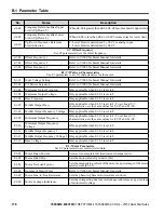


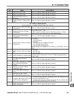


H2 Multi-Function Digital Output Settings
H2-
oo
Setting
Function
Description
4C
During Fast-stop
Closed: Fast-stop command is entered
4D
oH Pre-alarm Time Limit
Closed: oH Pre-alarm time limit is passed.
4E
Braking Transistor Fault (rr)
Closed: The built-in dynamic braking transistor failed.
Note:
Available in drive software versions PRG: 1016 and later.
4F
Braking Resistor Overheat (oH) Closed: The dynamic braking resistor overheated.
Note:
Available in drive software versions PRG: 1016 and later.
90 to 92 DriveWorksEZ Digital Output 1
to 3
These settings are for digital output functions used in DriveWorksEZ.
Normally there is no need to change or apply these settings.
100 to
192
H2 Parameter Functions
Reversed Output Switching of 0
to 92
Reverse the output switching of the multi-function output functions. Set
the last two digits of 1
oo
to reverse the output signal of that specific
function.
No.
Name
Description
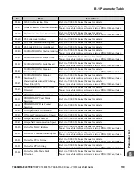
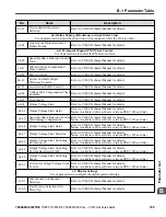
H3: Analog Inputs
Use H3 parameters to set the multi-function analog input terminals.
H3-01
Terminal A1 Signal Level Selection
0: 0 to +10 V (lower limit)
1: 0 to +10 V (no lower limit)
H3-02
Terminal A1 Function Selection
Sets the function of terminal A1.
H3-03
Terminal A1 Gain Setting
Sets the level of the input value selected in H3-02 when 10V is input
at terminal A1.
H3-04
Terminal A1 Bias Setting
Sets the level of the input value selected in H3-02 when 0V is input
at terminal A1.
H3-09
Terminal A2 Signal Level Selection
Sets the input signal level for terminal A2.
0: 0 to +10 V (with lower limit)
1: 0 to +10 V (no lower limit)
2: 4 to 20 mA
3: 0 to 20 mA
H3-10
Terminal A2 Function Selection
Sets the function of terminal A2.
H3-11
Terminal A2 Gain Setting
Sets the level of the input value selected in H3-10 when 10 V (20
mA) is input at terminal A2.
H3-12
Terminal A2 Bias Setting
Sets the level of the input value selected in H3-10 when 0 V (0 or 4
mA) is input at terminal A2.
H3-13
Analog Input Filter Time Constant
Sets the primary delay filter time constant for terminals A1 and A2.
Used for noise filtering.
H3-14
Analog Input Terminal Enable
Selection
Determines which analog input terminal or terminals will be enabled
when a digital input programmed for “Analog input enable” (H1
o
-
oo
= C) is activated.
1: Terminal A1 only
2: Terminal A2 only
7: All terminals enabled
Note:
Available in drive software versions PRG: 1016 and later.
B.1 Parameter Table
YASKAWA ELECTRIC TOEP C710606 47A YASKAWA AC Drive – V1000 Quick Start Guide
187
B
Parameter List


