background image

2-4

180788-1CD

HW1484370

2

Transport

2.1 Transporting Method

MPX2600

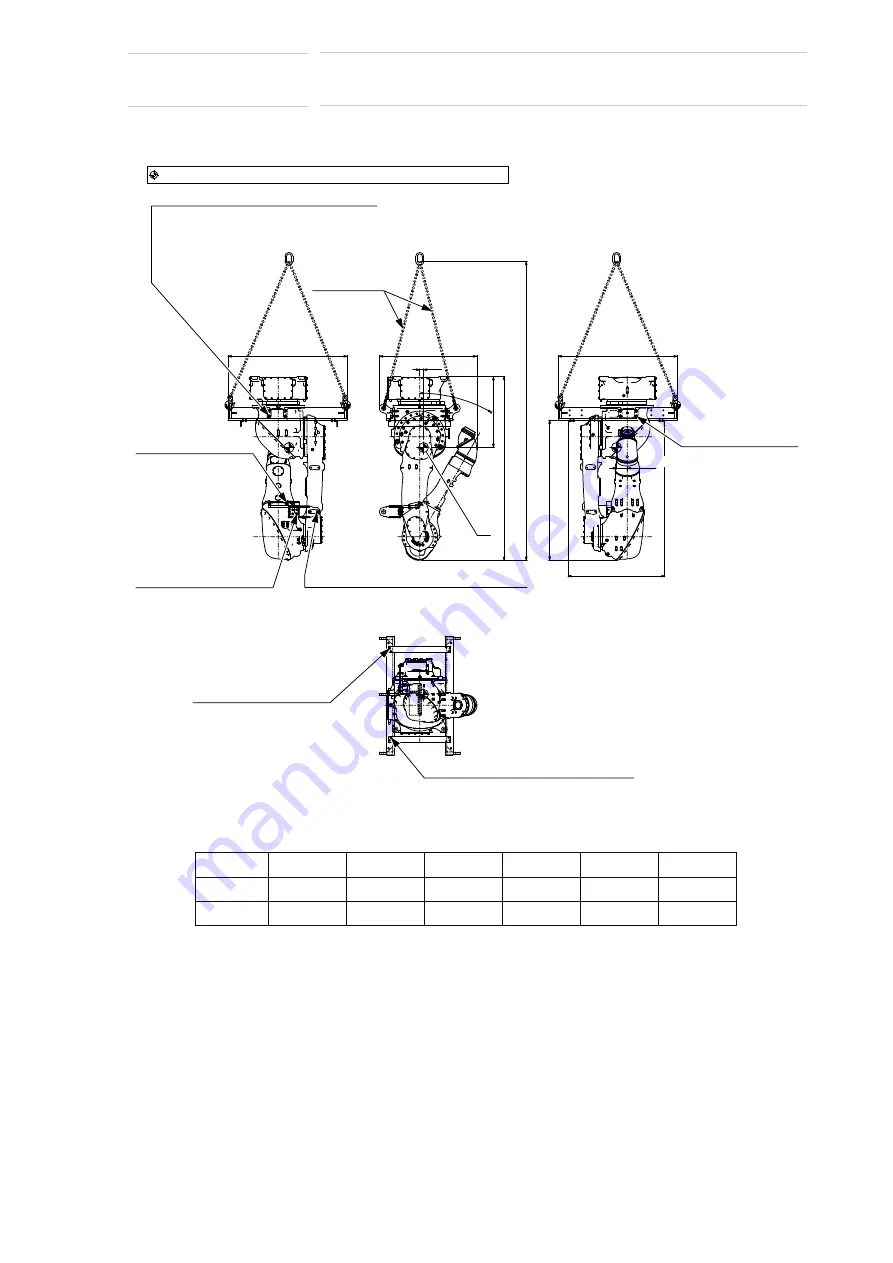
Fig. 2-1(c): Transport Using a Crane (Ceiling-mounted) (Optional)

The manipulator is in the nailed wooden box when it is delivered.

G

1190

(976)

(1833)

37.1

708.3

30

°

1190

(1398)

(965)

(2983)

108.1

0

-144625

0

T-axis

B-axis

0

R-axis

-60°

U-axis

0

L-axis

0

S-axis

Factory setting for angle and pulse of each axis

Axis

Angle

Pulse

:Gravity center “G” : Manipulator and Shpping bolts and brackets

Hexagon socket head cap screw M16
(4 screws, length: 50 mm)
Conical spring washer 2H-16 (4 washers)
Washer M16 (4 washers)
Tightening torque: 
206 N•m (21 kgf•m)

Hexagon socket head 
cap screw M10 
(2 screws,
 length: 35 mm)
Conical spring washer 
2L-10 (2 washers)
Tightening torque: 
48 N•m (4.9 kgf•m)

Hexagon socket head 
cap screw M10 
(4 screws, length: 35 mm)
Conical spring washer 
2L-8 (4 washers)
Tightening torque: 
24.5 N•m (2.5 kgf•m)

Hexagon socket head cap screw M10
(2 screws, length: 35 mm)
Conical spring washer 2L-10 (2 washers)
Tightening torque: 48 N•m (4.9 kgf•m)

Hexagon socket head 
cap screw M8 
(4 screws, length: 20 mm)
Conical spring washer 
2L-8 (4 washers)
Tightening torque: 
24.5 N•m (2.5 kgf•m)

Hexagon socket head cap screw M8 
(4 screws, length: 20 mm)
Conical spring washer 2L-8 (4 washers)
Tightening torque: 24.5 N•m (2.5 kgf•m)

Hexagon socket head 
cap screw M16
(4 screws,
 length: 50 mm)
Conical spring washer 
2H-16 (4 washers)
Washer M16 
(4 washers)
Tightening torque: 
206 N•m (21 kgf•m)

Wire Rope
length: 1.5 m 
or more

27 of 116

Summary of Contents for MOTOMAN-MPX2600

Page 1: ...in for future reference MOTOMAN MPX2600 INSTRUCTIONS MOTOMAN MPX2600 MAINTENANCE MANUAL MOTOMAN MPX2600 INSTRUCTIONS FOR MANIPULATOR OPTIONAL SPECIFICATIONS INSTRUCTIONS FOR EXPLOSION PROOF SPECIFICATIONS DX200 INSTRUCTIONS FOR EXPLOSION PROOF SPECIFICATIONS DX200 INSTRUCTIONS DX200 OPERATOR S MANUAL FOR PAINTING DX200 MAINTENACE MANUAL The DX200 operator s manual above corresponds to specific usa...

Page 2: ...ted property of YASKAWA and may not be sold or redistributed in any way You are welcome to copy this document to your computer or mobile device for easy access but you may not copy the PDF files to another website blog cloud storage site or any other means of storing or distributing online content Printed in the United States of America First Printing 2017 YASKAWA America Inc Motoman Robotics Divi...

Page 3: ...anual CAUTION Some drawings in this manual are shown with the protective covers or shields removed for clarity Be sure all covers and shields are replaced before operating this product The drawings and photos in this manual are representative examples and differences may exist between them and the delivered product YASKAWA may modify this model without notice when necessary due to product improvem...

Page 4: ...sible for providing adequately trained personnel to operate program and maintain the equipment NEVER ALLOW UNTRAINED PERSONNEL TO OPERATE PROGRAM OR REPAIR THE EQUIPMENT We recommend approved YASKAWA training courses for all personnel involved with the operation programming or repair of the equipment This equipment has been tested and found to comply with the limits for a Class A digital device pu...

Page 5: ...rsonnel CAUTION Indicates a potentially hazardous situation which if not avoided could result in minor or moderate injury to personnel and damage to equipment It may also be used to alert against unsafe practices MANDATORY Always be sure to follow explicitly the items listed under this heading PROHIBITED Must never be performed NOTE To ensure safe and efficient operation at all times be sure to fo...

Page 6: ...the manipulator Be sure to use a lockout device to the safeguarding when going inside Also display the sign that the operation is being performed inside the safeguarding and make sure no one closes the safeguarding View the manipulator from the front whenever possible Always follow the predetermined operating procedure Keep in mind the emergency response measures against the manipulator s unexpect...

Page 7: ... inspection procedures prior to conducting manipulator teaching If problems are found repair them immediately and be sure that all other necessary processing has been performed Check for problems in manipulator movement Check for damage to insulation and sheathing of external wires Always return the programming pendant to the hook on the cabinet of the DX200 after use The programming pendant can b...

Page 8: ...40Υ 320 L min 15 NL min 0 01㹼0 02 MPa 0 18㹼0 20 MPa 㕲ࣜࢳ 㟁ụ㸦ENERGIZER L91㸧 ෆᅽಖㆤࢩࢫࢸ ຍ ࡿ ౪ ᅽຊ ෆᅽಖㆤࢩࢫࢸ 50 kPa 5 kPa ෆᅽ KVA KW A 㠀ᮏᏳᅇ AC250V 50 60Hz DC250V チᐜ㟁ᅽ YR MPX2600 A00 8 7 9 9 3 0 Ex ibpxIIB T4 Gb Ex ibIIBT4Gb Ex ib IIB 15 NL min 㔞 ࣝ ࢳࣥヨ㦂 ᆺ ᘧ 㜵 グྕࠉ ᐃ ᱁ࠉ ࢽࣆࣗࣞ ࢱࠉ ᮏᏳᅇ ࣂࢵࢸࣜࣂࢵࢡ ࢵࣉᅇ DC4 5V 37 9mA ᅖ ᗘ 0Υ㹼 45Υࠉ ࠉࠉࠉ 1 ࢽࣆࣗࣞ ࢱࠊࣜࣞ ࣂࣜ ࠊ ࣂࣜ ཬࡧ ࣥࢥ ࢲศ㞳ᇶᯈ ሬ ࣘࢽࢵࢺෆⶶ ࡣ ᮏ Ᏻ 㜵 ᵓ㐀ཬࡧෆᅽ㜵 ᵓ㐀ࡢ ྜࡏᶵჾ ࡍ ࡽࠊᵓᡂᶵჾࠊ㓄 ࢆኚ ࡲࡓࡣ ᨵ㐀ࡋ ...

Page 9: ...18 to 0 20 MPa Setting Pressure for Operating 0 01 to 0 02 MPa Lithium Iron Disulfide Battery ENERGIZER L91 Battery backup circuit is consisted of battery unit position detector and encoder separation board The circuit is intrinsically safe circuit when the power supply of the Controller is shut down or air purging The painting Unit combined shall be grounded at 100 ohms or less Relay barrier isol...

Page 10: ...change any Parameters NJ4036 NJ4032 Crush hazard Can cause severe injury Keep clear of all moving parts はさまれ危険 重傷を負う恐れあり 動作中は手や身体を 近づけるな NJ4037 警 告 WARNING NJ4036 NJ4033 Collision hazard Can cause severe injury Keep away from the robot during automatic operation 衝突の危険 重傷を負う恐れあり 自動運転中は近づくな 警 告 WARNING NJ4032 PurgingPressure OperationPressure 0 0 1 0 3 0 2 0 4 SMC MPa 0 0 05 0 15 0 1 0 2 SMC MPa バッテ...

Page 11: ...tion manual of each manipulator MOTOMAN MPX2600 meets the following requirements IEC60079 0 for electrical apparatus for explosive gas atmospheres Part 0 General requirements IEC 60079 2 for electrical apparatus for explosive gas atmospheres Part 2 Pressurized enclosures p IEC60079 11 for electrical apparatus for explosive gas atmospheres Part 11 Intrinsic safety i In special cases such that the s...

Page 12: ...e MOTOMAN MPX2600 in the hazardous area classify the manipulator environment by following the local explosion proof standard and then on the basis of the explosion proof structure notation on the MOTOMAN MPX2600 confirm that the manipulator is possible to install in that area PROHIBITED Any modification of the MOTOMAN MPX2600 and the following is strictly prohibited 1 Explosion proof devices and s...

Page 13: ...The manipulator is in its standby position c When any abnormality occurs immediately press the emergency stop button to stop the manipulator d Before entering inside the manipulator working envelope be sure to stop the manipulator and turn OFF the main power supply to the DX200 Brake release Optional A braking system is provided on each axis of the manipulator to hold the arm in its position when ...

Page 14: ...t is not in use In accordance with ANSI RIA R15 06 2012 section 4 2 5 Sources of Energy use lockout tagout procedures during equipment maintenance Refer also to Section 1910 147 29CFR Part 1910 Occupational Safety and Health Standards for General Industry OSHA Mechanical Safety Devices The safe operation of this equipment is ultimately the users responsibility The conditions under which the equipm...

Page 15: ...backup must always be made before any service procedures are done and before any changes are made to options accessories or equipment Any modifications to the controller unit can cause severe personal injury or death as well as damage to the robot Do not make any modifications to the controller unit Making any changes without the written permission from YASKAWA will void the warranty Some operatio...

Page 16: ...ified personnel Summary of Warning Information This manual is provided to help users establish safe conditions for operating the equipment Specific considerations and precautions are also described in the manual but appear in the form of Dangers Warnings Cautions and Notes It is important that users operate the equipment in accordance with this instruction manual and any additional information whi...

Page 17: ...ly 24 to 36 hours for a response to your inquiry Please have the following information ready before you call Customer Support techsupport motoman com NOTE Please use e mail for routine inquiries only If you have an urgent or emergency need for service replacement parts or information you must contact YASKAWA Customer Support at the telephone number shown above System MPX2600 Primary Application __...

Page 18: ...r on the Baseplate 3 3 3 2 2 How to Install the Pressure Switch 3 4 3 3 Mounting methods 3 5 3 3 1 S axis Operation Range 3 5 3 3 2 Installing Direction 3 5 3 3 3 Measures to Prevent the Manipulator from Falling 3 6 3 4 Protection Class 3 7 3 5 Location 3 7 4 Wiring 4 1 4 1 Grounding 4 3 4 2 Cable Connection 4 5 4 2 1 Connecting Positions of Cables 4 8 4 2 2 Manipulator Cable Connection 4 10 4 2 3...

Page 19: ...Stop Category 1 S Axis 5 9 5 6 5 3 Stopping Distance and Time for Stop Category 1 L Axis 5 10 5 6 5 4 Stopping Distance and Time for Stop Category 1 U Axis 5 11 5 7 Modification of S Axis Movable Envelope 5 12 5 7 1 Changing the S axis Mechanical Stopper 5 13 5 7 2 Adjustment to the Pulse Limitation of S Axis 5 13 6 Allowable Load for Wrist Axis Flange 6 1 6 1 Allowable Wrist Load 6 1 6 2 Wrist Fl...

Page 20: ...xis Speed Reducer 10 12 10 2 2 Inspection of Air Sealing for Internal Air Pressure 10 13 10 2 3 Battery Replacement 10 15 10 3 Inspection of the Explosion Proof Device 10 17 10 3 1 Pressure Switch Unit Inspection 10 17 10 3 1 1 Solenoid Valve 10 17 10 3 1 2 Operation Method of Pressure Reducing Valve 10 17 10 3 1 3 Operation Check of Pressure Reducing Valve 10 18 10 3 1 4 Operation Check of Pressu...

Page 21: ...0 0 1 0 3 0 2 0 4 SMC MPa ࠉ 0 0 05 0 15 0 1 0 2 SMC MPa ࠉ ಖㆤ ࢫࡢ ᑠᤲẼὶ㔞 ᑠᤲẼ 㛫 ᑠෆᅽ ಖㆤ ࢫࡢ ᑠὶ㔞 ෆᅽಖㆤࢩࢫࢸ ຍ ࡿ ᑠ౪ ᅽຊ ෆᅽᐜჾධཱྀ ࡢಖㆤ ࢫࡢᣦᐃࡢ ᗘཪࡣ ᗘ ᅖ 㸲min 0 Υ㹼 40Υ 390L min 50NL min 㸦ሷ ࢳ ࢽࣝࣜࢳ 㟁ụ㸦ER17500VLY㸧 ෆᅽಖㆤࢩࢫࢸ ຍ ࡿ ౪ ᅽຊ ෆᅽಖㆤࢩࢫࢸ 206 2 l 50 kPa 5 kPa ෆᅽ KVA 3 5 KW 10 3 A 10 1 ෆᐜ DX200 MPX2600 ࢲࡢྠ NO ᥋ ࡋᚚ 㢪 ࡲࡍࠋ Motomanᮏయ ࢥࣥࢺࣟ ࣛࡣࠊୗグ ORDER NO ࠉ㝤 ឤ㟁ࡢᜍࢀ ࡾ 㟁 ࠊᡬࢆ㛤ࡅࡿ ࡢࢻ ࣟࢵࢡࢆ ᐇ 㛢ࡵ ୗࡉ ࠋ CHECK ALL THE DOOR LOCKS PROPERLY O...

Page 22: ... 12 mm 2 For mounting the bracket to the manipulator cable Conical spring washer M4 2 Hexagon socket head cap screw M5 Length 8 mm 2 For mounting the grounding wire of the manipulator cable Conical spring washer M5 2 Cable tie T50L 4 For tying up the plastic cover for the manipulator cable Hexagon socket head cap screw M6 Length 25 mm 14 For mounting the manipulator cable Conical spring washer M6 ...

Page 23: ...ࣞ ࣂࣜ ࠊ ࣂࣜ ཬࡧ ࣥࢥ ࢲศ㞳ᇶᯈ ไᚚ ෆⶶ ࡣ ᮏ Ᏻ 㜵 ᵓ㐀ཬࡧෆᅽ㜵 ᵓ㐀ࡢ ྜࡏᶵჾ ࡍ ࡽࠊᵓᡂᶵჾࠊ㓄 ࢆኚ ࡲࡓࡣ ᨵ㐀ࡋ ୗࡉ ࠋࠉ 3 ไᚚ ࡢ᥋ᆅࡣD ᥋ᆅᕤ ࡌ ࡗ ୗࡉ ࠋࠉ 4 ࣜࣞ ࣂࣜ ࠊ ࣂࣜ ཬࡧ ࣥࢥ ࢲศ㞳ᇶᯈ ไᚚ ෆⶶ ࡣ㠀 㝤ሙᡤ タ ࠉ ࡋ ୗࡉ ࠋࠉ ᰴᘧ ࠉᏳᕝ㟁ᶵࠉ 6 Ⓨᛶ㞺ᅖẼࡀᏑᅾࡍࡿ ࡑࢀࡢ ࡿ ࡁࡣ ࣂࢆ㛤ࡅ ୗࡉ ࠋ 7 ࡇࢀࡣࠊෆᅽ㜵 ᵓ㐀ࡢᐜჾ ࡿࠋ 8 ྲྀᢅㄝ ཧ ࡢࡇ ࠋ NJ 2 ࣂࢵࢸࣜࣂࢵࢡ ࢵࣉᅇ ࡣࠊࣂࢵࢸࣜࠊ ฟჾࠊ ࣥࢥ ࢲศ㞳ᇶᯈ ࡽ ᵓᡂࡉࢀࠊไᚚ ࡢ㟁 㐽 ࠊࡲࡓࡣᤲẼ ᮏᏳᅇ ࡿࠋ 5 ࣂࢵࢸࣜࡢ ࡣࠊ Ⓨᛶ㞺ᅖẼࡢᜍࢀࡀ ែࢆ ㄆࡋ ࠋ 03 㟁ຊ ᐜ㔞 㟁ὶ 㟁ᅽ 9 ᥋ ࡲࡓࡣ㟁 ౪ ࢆ 㛤ࡍࡿ๓ ࠊࡇࡢ ࣥࢡࣟ ࢪࣕ ࡽ ࡍ ࡢ ࡇࡾࢆྲྀࡾ㝖 ୗࡉ ࠋ MADE IN JAPA...

Page 24: ...ck that the eyebolts are securely fastened The weight of the manipulator is approximately 550 kg including the shipping bolts and brackets for the floor mounted model For the wall mounted model the weight of the manipulator is approximately 600 kg For the ceiling mounted model the weight of the manipulator is approximately 580 kg Use a wire rope strong enough to withstand the mass Mount the shippi...

Page 25: ... 0 T axis 0 B axis 0 0 R axis 60 U axis 0 0 L axis 0 0 S axis Factory setting for angle and pulse of each axis Axis Angle Pulse Gravity center G Manipulator and Shpping bolts and brackets Hexagon socket head cap screw M16 4 screws length 50 mm Conical spring washer 2H 16 4 washers Washer M16 4 washers Tightening torque 206 N m 21 kgf m Hexagon socket head cap screw M16 4 screws length 50 mm Conica...

Page 26: ...er 2H 16 4 washers Washer M16 4 washers Tightening torque 206 N m 21 kgf m Hexagon socket head cap screw M10 4 screws length 35 mm Conical spring washer 2L 10 4 washers Tightening torque 48 N m 4 9 kgf m Hexagon socket head cap screw M16 4 screws length 50 mm Conical spring washer 2H 16 4 washers Washer M16 4 washers Tightening torque 206 N m 21 kgf m Hexagon socket head cap screw M10 4 screws len...

Page 27: ... cap screw M10 2 screws length 35 mm Conical spring washer 2L 10 2 washers Tightening torque 48 N m 4 9 kgf m Hexagon socket head cap screw M10 4 screws length 35 mm Conical spring washer 2L 8 4 washers Tightening torque 24 5 N m 2 5 kgf m Hexagon socket head cap screw M10 2 screws length 35 mm Conical spring washer 2L 10 2 washers Tightening torque 48 N m 4 9 kgf m Hexagon socket head cap screw M...

Page 28: ...claws of the forklift into the entry of the shipping bolts and bracket Transport the manipulator slowly with due caution in order to avoid overturn or slippage Fig 2 2 a Transport Using a Forklift Floor mounted G 708 3 1833 Unit mm Fix the manipulator to the base for transportation by using 22 dia tapped hole 4 holes Pallet Manipulator base Hexagon socket head cap screw M20 4 screws Nut M20 4 nuts...

Page 29: ...20 1020 917 7 Forklift claw entries Shipping bolt and bracket Fixed to the manipulator before shipment U axis r Forklift claw entries Unit mm Gravity center G Manipulator and Shpping bolts and brackets 0 144625 0 0 T axis 0 B axis 0 0 R axis 60 U axis 0 0 L axis 0 0 S axis Factory setting for angle and pulse of each axis Axis Angle Pulse 29 of 116 ...

Page 30: ...0 L axis 0 0 S axis Factory setting for angle and pulse of each axis Axis Angle Pulse Pallet Manipulator base Hexagon socket head cap screw M16 6 screws Washer M16 12 washers Nut M16 6 nuts Fix the manipulator to the base for transportation by using 17 5 dia tapped hole 4 holes 3 places Forklift claw entries Pallet Unit mm Gravity center G Manipulator and Shpping bolts and brackets 30 of 116 ...

Page 31: ...50 560 2235 1190 965 1500 1226 7 0 144625 0 0 T axis 0 B axis 0 0 R axis 60 U axis 0 0 L axis 0 0 S axis Factory setting for angle and pulse of each axis Axis Angle Pulse Forklift claw entries Pallet Fix the jig with the wooden frame by using 17 5 dia tapped hole 4 holes Unit mm Gravity center G Manipulator and Shpping bolts and brackets 31 of 116 ...

Page 32: ... Before turning ON the power check to be sure that the shipping bolts and brackets have been removed The shipping bolts and brackets then must be stored for future use in the event that the manipulator must be moved again for relocation Hexagon socket head cap screw M16 4 screws length 50 mm Conical spring washer 2H 16 4 washers Washer M16 4 washers Tightening torque 206 N m 21 kgf m Shipping bolt...

Page 33: ...f m Hexagon socket head cap screw M8 4 screws length 30 mm Conical spring washer 2L 8 4 washers Tightening torque 24 5 N m 2 5 kgf m Hexagon socket head cap screw M8 4 screws length 30 mm Conical spring washer 2L 8 4 washers Tightening torque 24 5 N m 2 5 kgf m Hexagon socket head cap screw M10 2 screws length 35 mm Conical spring washer 2L 10 2 washers Tightening torque 48 N m 4 9 kgf m Hexagon s...

Page 34: ...rding Failure to observe this warning may result in injury or damage Install the manipulator in a location where the manipulator s tool or the workpiece held by the manipulator will not reach the wall safeguarding or DX200 when the arm is fully extended Failure to observe this warning may result in injury or damage Do not start the manipulator or even turn ON the power before it is firmly anchored...

Page 35: ...Manipulator Repulsion Force A baseplate flatness must be kept at 0 5 mm or less insufficient flatness of installation surface may deform the manipulator shape and affect its functional abilities For installation refer to section 3 2 1 Mounting the Manipulator on the Baseplate Fig 3 1 Manipulator Repulsion Force Table 3 1 Manipulator Repulsion Force Horizontal rotation Vertical rotation Repulsion f...

Page 36: ...uring the operation Refer to Fig 3 2 Mounting the Manipulator on the Baseplate Note that there are holes in the manipulator base for positioning or the fitting surface For reproducing the mounting position set the knock pin 12 dia is recommended or the fitting surface Fig 3 2 Mounting the Manipulator on the Baseplate 240 240 240 240 205 0 1 240 0 1 240 0 1 275 0 1 275 0 1 205 0 1 275 0 1 275 0 1 2...

Page 37: ... For the installation method refer to Fig 3 3 Installing the Pressure Switch Unit Fig 3 3 Installing the Pressure Switch Unit Bracket Installation position of the bracket is changed Screws for installation delivered with the manipulator Hexagon socket head cap screw M5 length 16 mm 4 scews Washer M5 4 washers Tightening torque 6 00 N m 0 6 kgf m Horizontal Installation Enlarged View of C Fixing pa...

Page 38: ...nted way S axis operation range Installing direction Measures to prevent the manipulator from falling 3 3 1 S axis Operation Range For the wall mounted way the S axis operating range is 90 For optional 3 3 2 Installing Direction For the installing direction of wall mounted way refer to the Fig 3 4 Installing Direction For optional Fig 3 4 Installing Direction 0 144625 0 0 T axis 0 B axis 0 0 R axi...

Page 39: ... 3 5 Precaution Against Falling for details Fig 3 5 Precaution Against Falling NOTE In case of using the wall ceiling mounted way inform YASKAWA of the matter when placing an order Be sure to contact your YASKAWA representative listed on the backcover of this instruction manual to perform a wall ceiling installation on site Manipulator base Hexagon socket head cap screw M20 4 screws Tightening str...

Page 40: ... from dust soot oil or water Free from corrosive gas or liquid or explosive gas or liquid Free from excessive vibration Vibration acceleration 4 9 m s2 0 5 G or less Free from large electrical noise plasma Free from the strong magnetic field Altitude 1000 m or less Flatness for installation 0 5 mm or less NOTE When the operation is started after the manipulator has been out of operation and left i...

Page 41: ...the movable type power cable replace it in every 24 000 hours regardless of any damages For the fixed type power cable it is recommend to replace it in every 36 000 hours regardless of any damages For the cable gland it is required to use the specified one for the explosion proof certification It is highly recommend to use the cable gland prepared by YASKAWA which is the exclusively one Also pleas...

Page 42: ...losion proof optional The pressure switch unit can be installed at a maximum of 20 m away from the manipulator When programming pendant is in use Cable Air line Ground resistance must be 100 Ω or less with independent ground connection Relay connector Power supply 3 phase AC200 220V 50 60Hz Programming pendant non explosion proof Painting unit DX200 Ground resistance must be 10 Ω or less with inde...

Page 43: ...g Method Pressure Switch Unit Fig 4 2 a Grounding Method Manipulator MANDATORY Do not use this line sharing with other ground lines or grounding electrodes for other electric power motor power welding devices etc Where metal ducts metallic conduits or distributing racks are used for cable laying ground in accordance with Electric Equipment Technical Standards 5 5 mm2 or more Bolt M8 Washer for gro...

Page 44: ...CD HW1484370 MPX2600 Fig 4 2 b Grounding Method Pressure Switch Unit Horizontal Installation Vertical Installation Cross recessed APS screw M5 Washer for grounding Delivered with the Manipulator 5 5 mm2 or more 5 5 mm2 or more 44 of 116 ...

Page 45: ...to be protected by the wire blade prepared by YASKAWA length should be specified or to be put either in the ditch on the floor and be covered with the metal plate or through the metal pipe CAUTION Air tubes for purging are connected to the cover part of the power cables In case the tube is bent or foreign substances are stuck inside the tube air may not be appropriately supplied which would result...

Page 46: ... 5 6 2BC 1 2 3 4 5 6 Air supply Install the pressure switch unit outside of the motion range of the manipulator The maximum length of the air tube between the pressure switch unit and the manipulator is 20 m Prepare an air tube which is made of nylon and has an outside diameter of 16 mm 1 For the connecting position to the DX200 refer to fig 4 4 Manipulator Cable Connection DX200 side 2 For mounti...

Page 47: ...ipulator Cable Connection DX200 side INTRINSI CALLY SAFE INTRINSI CALLY SAFE Back Side of the DX200 X11 X21 1 Notation on the manipulator cable connection part varies depending on the DX200 specifications Select one of four cables for intrinsic safety and connect it 47 of 116 ...

Page 48: ...on Type Connecting position Remarks Standard type C Type Center Type Connect to the back side of the manipulator Refer to C type in Fig 4 5 Manipulator Cable Connecting Position Changeable L Type Left Type Viewing from the backside connect to the left side of the manipulator Refer to L type in Fig 4 5 Manipulator Cable Connecting Position Changeable R Type Right Type Viewing from the backside conn...

Page 49: ... the manipulator Refer to L type in Fig 4 6 Battery Mounting Position Changeable C Type Center Type Connect to the back side of the manipulator Refer to C type in Fig 4 6 Battery Mounting Position Changeable R Type Right Type Viewing from the backside connect to the right side of the manipulator Refer to R type in Fig 4 6 Battery Mounting Position 1 2 3 Changeable C Type Standard type L Type Chang...

Page 50: ...anipulator cable cover 7 Mount the gasket pressure of the manipulator cable to the base so that the protective gas force feeding tube does not bend inside the manipulator and then mount the cover by using the hexagon socket head cap screws M6 Fig 4 7 a Manipulator Cable Connection Standard Specification C Type Standard type C Type AIR IN 2BC cable Base Manipulator cable Tapped hole to connect the ...

Page 51: ...ble Connection L Type Fig 4 7 c Manipulator Cable Connection R Type L Type Manipulator cable Back side of the base Manipulator cable AIR IN 2BC cable Base 1BC cable View A A R Type Manipulator cable AIR IN 2BC cable Base Manipulator cable Back side of the base 1BC cable View A A 51 of 116 ...

Page 52: ...lent chromium 14 washers fixed to the manipulator Tightening torque 10 N m 1 0 kgf m C TYPE Cover R TYPE Hexagon socket head cap screw M3 4 screws length 10 mm fixed to the manipulator Conical spring washer 2L 3 4 washers fixed to the manipulator Tightening torque 1 4 N m 0 14 kgf m Base Cover Hexagon socket head cap screw M6 Trivalent chromium 14 screws length 25 mm fixed to the manipulator Conic...

Page 53: ...For terminal block 1 to 2 2 Cable connection 1 Intrinsically safe cable 1 Cable type applied CVV S 1 25 mm 2 4 6 8 10 12 cores CVV SB 1 25 mm 2 4 6 8 10 12 cores or UL2586 SB 1 25 mm 2 4 6 8 10 12 cores SUMIDEN HITACHI CABLE Ltd Note The barriers between P2 and N2 in the DX200 are short circuited by the wire Do not remove the wire On the manipulator side however since a short circuit does not exis...

Page 54: ...t peak 2 Air supply Pressurized explosion proof construction Required pressure 0 35 MPa to 0 65 MPa Capacity For pressurized type of explosion protected construction At operating 15 NI min or more At purging 1000 Nl min or more Dryness Freezing at 18 C Use dry air for the pressurized explosion proof construction 3 Grounding Grounding resistance 100 Ω or less For the DX200 CAUTION Use dry air for t...

Page 55: ...ressure Switch Unit Set the air pressure so that the pressure shown on the pressure gauge of each pressure reducing valve to be within the pressure ranges shown in fig 4 10 Fig 4 10 Electrical Air Circuit of the Pressure Switch Unit Intrinsically safe terminal block 320 L min 20 kPa 50 kPa 5 kPa Pressure switch unit Mnipulator AV1 SV1 Master Valve Purge pressure regulator Operating pressure purge ...

Page 56: ...ent Temperature Maximum Ambient Humidity Manipulator explosion proof 0 to 40 C 80 RH DX200 not explosion proof 0 to 45 C 90 RH Pressure Switch unit explosion proof 0 to 40 C 85 RH Programming pendant not explosion proof 0 to 40 C 85 RH Programming pendant explosion proof Optional 0 to 40 C 85 RH DANGER In case installing the MOTOMAN MPX2600 in the hazardous area classify the manipulator environmen...

Page 57: ...360 s B axis 6 28 rad s 360 s T axis 6 28 rad s 360 s Allowable Moment4 4 For details on the allowable moment and the allowable inertia refer to section 6 1 Allowable Wrist Load R axis 93 2 N m 9 5 kgf m B axis 58 8N m 6 0 kgf m T axis 19 6 N m 2 0 kgf m Allowable Inertia GD24 4 R Axis 3 75 kg m2 B Axis 2 225 kg m2 T Axis 0 20 kg m2 Approx Mass 485 kg Protective Structure Basic axis IP4X Wrist axi...

Page 58: ...5 Basic Specifications 5 2 Part Names and Working Axes 5 2 180788 1CD HW1484370 MPX2600 5 2 Part Names and Working Axes Fig 5 1 Part Names and Working Axes S L L U U R R T T B B S 58 of 116 ...

Page 59: ...600 5 3 Manipulator Base Dimensions Fig 5 2 Base Dimensions 22 dia hole 4 holes for installation S axis rotation center Unit mm 240 240 240 240 205 0 1 240 0 1 240 0 1 275 0 1 275 0 1 205 0 1 275 0 1 275 0 1 275 0 1 25 25 12 dia 2 holes 0 018 0 Fitting surface Fitting surface 59 of 116 ...

Page 60: ... 767 2000 423 0 1409 1643 1423 846 0 P Point P point maximum envelope 94 1813 1726 151 518 134 124 423 Unit mm 1000 328 90 6 5 65 1000 600 1 5 0 30 31 1 3 0 150 1 5 0 R2000 180 90 1775 90 90 755 6 550 R522 993 5 30 DANGER Each part of the manipulator can extend within the range of the P point maximum envelope shown in Fig 5 3 Dimensions and P point Maximum Envelope at maximum Take special consider...

Page 61: ...Purging pressure 0 18 to 0 20 MPa Operating pressure 0 01 to 0 02 MPa Air inlet 0 35 to 0 65 MPa tube 16 dia Air inlet From the manipulator tube 16 dia To the manipulator tube 16 dia Exhaust port 210 8 5 407 5 398 9 200 8 207 9 256 6 ユニファイ並目 六角ボルト5 16 18X1 ユニファイ並目 六角ナット5 16 18 KQ2L16 02S M 5 X 8 M4 M5 M5 M5X8 M5X8 M5X8 M5X8 M3X6 M3X6 ユニファイ並目 六角ボルト5 16 18X1 M4 K Q 2 L 1 6 0 2 S K Q 2 L 1 6 0 2 S M4...

Page 62: ...r stopping distance Stopping distance and stopping time are measured in accordance with ISO 10218 1 Annex B Stop categories According to IEC60204 1 Stop category 0 Stop category 1 The values specified for Stop category 0 are the reference values that are determined by tests and simulations The actual stopping distance and stopping time may differ 5 6 2 Definition of Use Load Rated load weight and ...

Page 63: ...ion Fig 5 5 b L Axis Extension and Fig 5 5 c U Axis Extension for each axis arm extension Fig 5 5 a S Axis Extension Fig 5 5 b L Axis Extension S axis L axis U axis R axis S axis L axis S axis L axis U axis R axis T axis T axis U axis R axis B axis T axis 66 33 100 2000 B axis B axis S axis L axis S axis L axis S axis L axis U axis U axis U axis R axis B axis T axis R axis T axis R axis B axis 100...

Page 64: ...5 Basic Specifications 5 6 Stopping Distance and Time for S L and U Axes 5 8 180788 1CD HW1484370 MPX2600 Fig 5 5 c U Axis Extension S axis L axis U axis T axis R axis 100 1000 B axis 64 of 116 ...

Page 65: ... 120 140 Stopping distance deg Extension 100 0 0 0 1 0 2 0 3 0 4 0 5 0 6 0 20 40 60 80 100 120 140 Stopping time sec Extension 100 Speed deg s Load100 Load66 Load33 Speed deg s Load100 Load66 Load33 0 10 20 30 40 50 0 20 40 60 80 100 120 140 Stopping distance deg Extension 66 0 0 0 1 0 2 0 3 0 4 0 5 0 6 0 20 40 60 80 100 120 140 Stopping time sec Extension 66 Speed deg s Load100 Load66 Load33 Spee...

Page 66: ...eed deg s Load100 Load66 Load33 Speed deg s Load100 Load66 Load33 0 10 20 30 40 50 0 20 40 60 80 100 120 140 Stopping distance deg Extension 66 0 0 0 1 0 2 0 3 0 4 0 5 0 6 0 20 40 60 80 100 120 140 Stopping time sec Extension 66 Speed deg s Load100 Load66 Load33 Speed deg s Load100 Load66 Load33 0 10 20 30 40 50 0 20 40 60 80 100 120 140 Stopping distance deg Extension 33 0 0 0 1 0 2 0 3 0 4 0 5 0...

Page 67: ...0 5 6 5 4 Stopping Distance and Time for Stop Category 1 U Axis 0 0 0 1 0 2 0 3 0 4 0 5 0 6 0 20 40 60 80 100 120 140 Stopping time sec Extension 100 0 10 20 30 40 50 0 20 40 60 80 100 120 140 Stopping distance deg Extension 100 Speed deg s Load100 Load66 Load33 Speed deg s Load100 Load66 Load33 67 of 116 ...

Page 68: ...cessary contact your YASKAWA representative in advance Fig 5 6 Components of the S Axis Stopper and Stopper Mounting Position Table 5 2 S Axis Operating Range Item Specifications S Axis Operating Range 150 150 standard 120 120 90 90 60 60 30 30 Base Rotating head Stopper for the fixing side Stopper position standard specification Hexagon socket head cap screw M20 length 45 mm Conical spring washer...

Page 69: ...ON the DX200 power supply Move the rotating axis to a position where the stopper can be mounted Then turn OFF the DX200 power supply and mount the mechanical stopper 5 7 2 Adjustment to the Pulse Limitation of S Axis For altering the range of motion of the S axis refer to section 8 17 Changing the Parameter in DX200 INSTRUCTIONS 165292 1CD Change the parameter as shown below by using the programmi...

Page 70: ...le Angle for S Axis Stopper Table 5 3 The Settable Angle for S Axis Stopper indicates the angle range which allows S axis to be set for direction and direction angles Ex 90 to 90 is settable however 0 to 150 is not settable Settable angle Non settable angle The Angle of S Axis Stopper for Direction 150 120 90 60 30 0 30 60 90 120 150 150 120 90 60 30 0 30 60 90 120 150 The Angle of S Axis Stopper ...

Page 71: ...ment arm rating shown in Fig 6 1 Moment of Arm Rating The allowable total moment of inertia is calculated when the moment is at the maximum Contact your YASKAWA representative beforehand when the moment of inertia is the only load or the load moment is smaller than moment of inertia Also when the load is combined as a force but a mass contact your YASKAWA representative Fig 6 1 Moment of Arm Ratin...

Page 72: ...he wrist flange dimensions are shown in Fig 6 2 Wrist Flange Fitting depth of inside and outside fittings must be 21 mm or less Fig 6 2 Wrist Flange Unit mm 140 dia 0 02 51 0 02 51 P C D 102 70 dia 0 1 21 5 dia 0 035 0 116 Six holes Depth 12 Pitch 1 0 Tapped hole M6 dia 0 0 012 5 2 Depth 10 2 holes 72 of 116 ...

Page 73: ...wn in Fig 7 1 Installing Peripheral Equipment for easier installation of the users system applications The following conditions shall be observed to attach or install peripheral equipment 7 1 1 Allowable Load The device required for the system application can be mounted on the upper arm U arm and the lower arm L arm Observe the following restrictions Total payload for the upper arm U arm and the l...

Page 74: ...mm or less Tapped holes M8 4 holes 2 places depth 20 mm pitch 1 25 Tapped holes M8 4 holes depth 20 mm pitch 1 25 Tapped holes M16 4 holes depth 36 mm pitch 2 0 Tapped holes M8 4 holes depth 21 mm pitch 1 25 Tapped holes M16 4 holes depth 36 mm pitch 2 0 Tapped holes M8 2 holes depth 20 mm pitch 1 25 View C Tapped holes M8 8 holes depth 21 mm pitch 1 25 Tapped holes M8 4 holes depth 20 mm pitch 1 ...

Page 75: ... Equipment Specification 8 1 Internal Connections MPX2600 8 Electrical Equipment Specification 8 1 Internal Connections The Fig 8 1 a Internal Connection Diagram Fig 8 1 b Internal Connection Diagram show the internal connections 75 of 116 ...

Page 76: ...ATA 2 5V 2 0V 2 FG2 DATA 3 DATA 3 X11 6X6 CN1 1 CN1 2 CN1 4 CN2 1 CN1 3 DATA 1 DATA 1 0V 1 DATA 2 5V 1 CN1 5 FG1 CN3 5 FG3 CN4 5 FG4 CN5 5 FG5 P S IRV 0 5XK S IRV 0 5XK S IRV 0 5XK 3 2 CN 1 No 6CN S IRV 0 3XK S IRV 0 3XK S IRV 0 3XK S IRV 0 3XK S IRV 0 3XK S IRV 0 3XK S IRV 0 3XK KIVTW 3 0 75XG Y KIVTW 3 0 75XG Y KIVTW 3 0 75XG Y KIVTW 3 0 75XG Y KIVTW 3 0 75XG Y KIVTW 3 0 75XG Y KIVTW 6 1 25XG Y ...

Page 77: ...4 2 YB MV4 MW4 MU4 3 2 No 21CN CN 1 SM ME5 BA5 BB5 1 2 YB MV5 MW5 MU5 No 23CN SM ME6 BA6 BB6 1 2 YB MV6 MW6 MU6 No 25CN SM 4 ME3 BB3 BA3 5 6 MU3 MV3 MW3 CN 1 No 11CN 2 3 B MV2 ME2 BA2 MW2 BB2 D 1 C 2 MU2 No 9CN CN A BB1 ME1 BA1 2 D 1 MV1 MU1 MW1 B CN A No 7CN C SM YB L AXIS YB SM S AXIS No 8CN No 10CN No 22CN No 24CN No 26CN D ME3 BB3 BA3 1 2 MU3 MV3 MW3 CN A No 19CN B C YB SM U AXIS No 20CN 4 3 2...

Page 78: ... cracks are found immediately stop the operation and contact your YASKAWA representatives 2 Motion Smooth tuning horizontal and vertical motions of each arm The robot s home position does not change Do not enter the robot working envelope 3 Noise and vibration during operation No abnormal noise and vibration during robot operation Do not enter the robot working envelope 4 Tubes Off or no severe we...

Page 79: ...the emergency stop button is pressed Inspect the manipulator while it is in its standby position and not in motion 2 Remove any dried paint from the emergency stop button Pressure Switch Unit 1 Pressure set value The pressure of the pressure reducing valve is within the specified range Do not make any modifications to the settings The pressure switch unit is a safety related parts for explosion Pr...

Page 80: ... air leakage from the tubes for air exhaust the couplings and the joint fittings of the motor on each axis when the air is supplied in the manipulator to form the anti explosion barrier The actual amount of air leakage is not important if a fault in the internal air pressure does not occur However if internal air pressure faults occur frequently check if the pressure of the air source and the pres...

Page 81: ...rgency stop button 9 2 2 Pressure Switch Unit 9 2 2 1 Pressure Before moving the manipulator check if the gauge of the pressure reducing valves on the pressure switch unit show the pressure to be within the specified range Pressure reducing valve for purging pressure 0 18 to 0 20 MPa Pressure reducing valve for the operating pressure 0 01 to 0 02 MPa CAUTION Paint stuck on the manipulator rotating...

Page 82: ...service company personnel Only specified personnel are to do inspection work DANGER Maintenance and inspection must be performed by specified personnel Failure to observe this caution may result in electric shock or injury For disassembly or repair contact your YASKAWA representative Do not remove the motor and do not release the brake Failure to observe these safety precautions may result in deat...

Page 83: ...t if any 5 Pressure switch unit setting Visual Check the value if it is within the proper value range 6 Base mounting bolts Spanner Wrench Tighten loose bolts Replace if necessary 7 Cover mounting screws Wrench Tighten loose bolts Replace if necessary 8 S L and U axis motors Visual Check for grease leakage 2 9 Motor connectors Manual Check for loose connectors 10 Motor part Visual Check for filter...

Page 84: ...Confirm that the pressure switch flow switch solenoid valve and the pressure reducing valve operate correctly Contact your YASKAWA representatives 21 Overhaul 1 Inspection No correspond to the numbers in Fig 10 1 Inspection Parts and Inspection Numbers 2 The occurrence of a grease leakage indicates the possibility that grease has seeped into the motor This can cause a motor breakdown Contact your ...

Page 85: ...ion Numbers Table 10 2 Inspection Parts and Grease Used No Grease Used Inspected Parts VIGO Grease RE No 0 S L U R B and T axis speed reducers Alvania EP Grease 2 Wrist gear 17 18 19 17 12 11 7 10 18 14 19 9 11 7 11 7 11 7 11 7 11 17 17 13 13 14 7 10 9 8 10 9 8 6 15 20 16 Pressure switch unit mounted separately 5 3 85 of 116 ...

Page 86: ...r apply Alvania EP grease 2 on the gear teeth of gears R1 B1 B2 T1 T2 and T3 by using a grease gun Apply seal tape on the thread part of each plug then reinstall the plugs Each plug must be tightened with the specified tightening torque Fig 10 2 Wrist Gears Hexagon socket head cap screw M4 trivalent chromium length 12 mm 6 screws Conical spring washer 2H 4 trivalent chromium 6 washers Tightening t...

Page 87: ...for discharging the grease set air supply pressure at 0 025 MPa or less If the air supply pressure is higher than above mentioned value an oil seal of a speed reducer will come off and it may result in a failure 4 When using extrusion air for discharging grease grease may be vigorously discharged from the exhaust port Perform an operation such as using a tube at the grease exhaust port to pour int...

Page 88: ...tainless Tightening torque 23 N m 2 34 kgf m Grease exhaust port S axis Plug PT3 8 Stainless Tightening torque 23 N m 2 34 kgf m Grease inlet S axis Plug PT3 8 Stainless Tightening torque 23 N m 2 34 kgf m Grease inlet S axis Plug PT3 8 Stainless Tightening torque 23 N m 2 34 kgf m Grease exhaust port S axis Plug PT3 8 Stainless Tightening torque 23 N m 2 34 kgf m Grease inlet L axis Plug PT3 8 St...

Page 89: ... 34 kgf m Grease exhaust port S axis Plug PT3 8 Stainless Tightening torque 23 N m 2 34 kgf m Grease exhaust port L axis Plug PT3 8 Stainless Tightening torque 23 N m 2 34 kgf m Grease inlet L axis Plug PT3 8 Stainless Tightening torque 23 N m 2 34 kgf m Grease inlet U axis Plug PT3 8 Stainless Tightening torque 23 N m 2 34 kgf m Grease exhaust port U axis Plug PT3 8 Stainless Tightening torque 23...

Page 90: ... Inject the grease through the grease inlet using a grease gun Grease type VIGO grease RE No 0 Recommended grease lubricator Powerlube P3C made by Macnaught Amount of grease 7 g s or less For example if grease is supplied from the lubricator at 2 times s set the amount to 3 5 g time or less Air supply pressure of grease pump Approximately 0 3 MPa or less Table 10 4 Amount of Grease 5 The old greas...

Page 91: ...se is not discharged enough by injecting air operate the manipulator about 5 times in the teach mode as shown in Table 10 6 Grease Discharging Operation for Each Axis Method 2 Suctioning grease out 1 Keep the inlet open and insert the tube into the exhaust port 2 Discharge grease by suctioning grease out of the exhaust port Suction pressure 0 025 MPa or less 3 If grease is not discharged by suctio...

Page 92: ...icated in Fig 10 4 Grease Receiving Bag Rough Standard and then perform the running in operation Fig 10 4 Grease Receiving Bag Rough Standard 8 Wipe the discharged grease with a cloth and reinstall the plug Clean and degrease the tap part and the thread part of the plug Wrap the seal tape TB4501 around the plug attach it to the grease inlet and then tighten the plug with the designated tightening ...

Page 93: ...ease with the cloth when the grease is discharged completely and reinstall the plug Apply seal tape on the thread part of each plug Fig 10 5 R B and T axes Speed Reducer NOTE If grease is injected with the plug Ro Bo To on the grease will go inside the motor and may cause a damage Make sure to remove the plug Ro Bo To before the grease injection Note that grease replacement is not necessary for R ...

Page 94: ...0 6 Gasket in Base Part Inspection NOTE Perform 3 1 Checking of Purging Operations in section 10 3 2 Enclosure Protection Sequence after gasket is replaced Base Base Gasket Adhered to the cover Gasket Adhered to the cover Cover Hexagon socket head cap screw M6 trivalent chromium length 25 mm 14 screws Conical spring washer 2H 6 trivalent chromium 14 washers Tightening torque 10 N m 1 0 kgf m Gaske...

Page 95: ...m Gasket Adhered to the cover Cover Gasket Adhered to the cover Gasket Adhered to the cover Cover Hexagon socket button head screw M8 length 25 mm 13 screws Conical spring washer 2H 8 trivalent chromium 13 washers Cover Hexagon socket button head screw M8 length 25 mm 10 screws Conical spring washer 2H 8 trivalent chromium 10 washers Hexagon socket button head screw M8 length 25 mm 8 screws Conica...

Page 96: ...ck turn OFF the power supply to the DX200 and check that no explosive atmosphere exists around the battery pack Hexagon socket head cap screw M6 trivalent chromium length 25 mm 14 screws Conical spring washer 2H 6 trivalent chromium 14 washers Tightening torque 10 N m 1 0 kgf m Hexagon socket head cap screw M4 length 85 mm 2 screws Washer M4 trivalent chromium 2 washers Tightening torque 1 2 N m 0...

Page 97: ...ies before disconnecting the old one so that the data does not disappear BAT 1 BAT 1 BAT 1 BAT 1 BAT 3 BAT 3 BAT 3 BAT 3 BAT 5 BAT 5 BAT 5 BAT 5 Battery for S L axis bofore replacement See step 7 below See step 8 below See step 5 below New battery board See step 6 below Battery for U R axis bofore replacement See step 6 below See step 7 below See step 5 below New battery board See step 6 below Bat...

Page 98: ...he value follow the procedures below 1 Turn OFF the power supply to the DX200 2 Unscrew the hexagon socket head cap screws to remove the pressure unit cover Refer to Fig 10 10 Pressure Switch Unit Cover 3 Loosen the locking nut equipped to the valves with a spanner nominal size 10 mm Refer to Fig 10 11 Operation Methods of Pressure Reducing Valve 4 Adjust the dial on the valve to modify the value ...

Page 99: ... valves as shown in Table 10 9 List of Setting Value for Pressure Reducing Valve for Purging Pressure and OperatingPressure Refer to section 10 3 1 2 Operation Method of Pressure Reducing Valve for the reducing valve operation 5 Turn ON the power supply to the DX200 and start purging Check that the pressure is keeping between 0 18 MPa and 0 20 MPa while purging 6 After purging is complete wait for...

Page 100: ... 0 2 SMC MPa ࠉ Pressure reducing valve for purging pressure SV1 FS 0 0 1 0 3 0 2 0 4 SMC MPa ࠉ 0 0 05 0 15 0 1 0 2 SMC MPa ࠉ Pressure adjusting tit Locking nut Tigntening tool Spanner nominal size 10 mm Pressure reducing valve for operating pressure Industrial compressed air 0 35 to 0 65 MPa From manipulator Air tube outside 16 dia inside 12 dia Pressure gauge To manipulator Air tube outside 16 di...

Page 101: ...OperatingPressure Refer to section 10 3 1 2 Operation Method of Pressure Reducing Valve for the pressure reducing valve operation 4 Remove the clear cover from the pressure switch unit terminal box and then connect a metering rod which is a multimeter To P1 connect side of the metering rod and side to N1 Refer to Fig 10 13 Operation Check for Pressure Detector 5 Confirm that conduction is not prod...

Page 102: ...at the flow meter indicates 5 L min when the operating pressure is 0 05 MPa 6 Set the pressure of operation air reducing valve as shown in Table 10 12 Reducing Valve for Operating Pressure Adjusting Pressure 2 Refer to section 10 3 1 2 for the pressure reducing valve operation 7 Check that the flow meter indicates 0 L min when the operating Pressure is 0 02 MPa 8 Remove the flow meter 9 Set the pr...

Page 103: ...ct a multimeter metering rod side A Part Enlarged View Section A A Industrial compressed air 0 35 to 0 65 MPa A part Pressure reducing valve for purging pressure 0 18 to 0 20 MPa Pressure reducing valve for operating pressure 0 01 to 0 02 MPa Exhaust side of pressure adjusting valve The size of the plug is Rc1 4 SV1 FS 0 0 1 0 3 0 2 0 4 SMC MPa ࠉ 0 0 05 0 15 0 1 0 2 SMC MPa ࠉ AV1 PS3 PS1 Pressure ...

Page 104: ...hat purging operation starts a few seconds later 5 While purging check that air is exhausted from the master valve exhaust port Note that air is also exhausted from pressure adjusting exhaust port Refer to Fig 10 15 Operation Check for Master Valve 6 Turn OFF the power supply to the DX200 again and re install the cover with the hexagon socket head cap screws Refer to Fig 10 10 Pressure Switch Unit...

Page 105: ...closure protection sequence is composed of the following four modes 1 Preparation Mode 2 Purging Mode 3 Operation Mode 4 Shut down Mode Supply the protective gas after the following inspection Loosen bolts to enclosures Any damages to the enclosure Start supplying the protective gas into the pressure switch unit The protective gas is regulated in proper values by the reducer valve to operate then ...

Page 106: ... pendant 4 Supplying of the power becomes available to motors brakes and painting device After these steps the mode is switched to the operation m ode Purging Mode C D Y N Y Start Purging Mode 1 Switch the operation pressure to the purging pressure 2 Release the master valve When the purging air is 20 kPa or more has the flow reached 320 L min Abnormal Pressure Mode Execute Abnormal Pressure Mode ...

Page 107: ...tor PS1 is opened the hardware circuit power control cirtuit purging control relay and encoder separation board is turned OFF And the servo unit encoder and painting device power sources are autmatically shut down In case the abnormal pressure LOW occurs during the purging mode the master valve is automatically shut OFF to prevent the dangerous gas from infowing Abnormal Pressure LOW is displayed ...

Page 108: ...ion pressure MPa Purging Pressure MPa Details 0 01 to 0 02 0 18 to 0 20 Confirm the setting value of pressure switch unit operating pressure and purging pressure Each value should be within the range shown in the left Turn ON the power supply to the DX200 Purging start and the message Air Purging is indicated on the programing pendant window While purging confirm that no power is supplied to motor...

Page 109: ...f While the abnormal pressure Low error alarm is occurred confirm that the power supply is not turned ON and the manipulator is inoperable even SERVO ON READY on the programming pendant is pressed and the enable switch is gripped 5 2 3 4 5 1 2 3 4 5 3 3 Checking the Inner Pressure Error high pressure error Detection Operations Checking item in the above mentioned checking 3 1 Abnormal inner pressu...

Page 110: ... Alarm Impossible to resume operations No Operation pressure MPa Purging Pressure MPa Details 0 01 0 02 0 18 0 20 Confirm the setting value of pressure switch unit operating pressure and purging pressure Each value should be within the range shown in the left Turn ON the power supply to the DX200 Purging start and a message Air Purging is indicated on the programing pendant window While purging co...

Page 111: ...ct pin terminal is mounted on the encoder connector of each motor Refer to Fig 10 17 a Backup Battery Connection for S L and U Axis Motors Fig 10 17 b Backup Battery Connection for R B and T Axis Motors and connect the battery pack according to the following procedure 1 Connect the battery to the connectors for the battery backup of the motor encoder connector 2 Confirm all connectors connection a...

Page 112: ...tery for backup Power connector Motor Encoder connector b a a b BAT OBT BAT OBT Connection Diagram b a a b Caution label 0BT BAT 0BT BAT Connect battery to encoder to save the data before removing connector CAUTION Internal cables a Crimped contact pin pin b Crimped contact pin socket Connect battery to encoder to save the data before removing connector CAUTION CAUTION label Enlarged view 112 of 1...

Page 113: ...ector a b BAT OBT Caution label Encoder Filter Motor cable etc B T Axis Motor Power connector Motor Encoder connector a b BAT OBT Connect battery to encoder to save the data before removing connector CAUTION Internal cables Internal cables Connect battery to encoder to save the data before removing connector CAUTION Connect battery to encoder to save the data before removing connector CAUTION CAUT...

Page 114: ...2 Rank Parts No Name Type Manufacturer Qty Qty per Unit Remarks A 1 Battery pack HW1372692 A YASKAWA Electric Corporation 1 1 For S L axis encoder A 2 Battery pack HW1372692 B YASKAWA Electric Corporation 1 1 For U R axis encoder A 3 Battery pack HW1372692 C YASKAWA Electric Corporation 1 1 For B T axis encoder A 4 Sealing compound DB 1600 Diabond Industry Co Ltd 200ml For gasket cohesion A 5 Seal...

Page 115: ...on 1 1 Inside U axis B 13 Lead wire for U axis encoder HW1372336 A YASKAWA Electric Corporation 1 1 Inside U axis B 14 Wrist unit HW1171980 C YASKAWA Electric Corporation 1 1 C 15 S L axis AC servo motor SGMRV 37ANA YRA2 YASKAWA Electric Corporation 1 2 C 16 U axis AC servo motor SGMRV 13ANA YRA1 YASKAWA Electric Corporation 1 1 C 17 R B T axis AC servo motor SGMAV 04ANA YR22 YASKAWA Electric Corp...

Page 116: ...rgaon Haryana India Fax 91 124 475 8542 Phone 91 124 475 8500 YASKAWA India Private Ltd Robotics Division YASKAWA Electric China Co Ltd 22F One Corporate Avenue No 222 Hubin Road Huangpu District Shanghai 200021 China Phone 86 21 5385 2200 Fax 㸩86 21 5385 3299 YASKAWA Electric Thailand Co Ltd 59 1st 5th Floor Flourish Building Soi Ratchadapisek 18 Ratchadapisek Road Huaykwang Bangkok 10310 THAILAN...

Reviews: