background image

3

SECTION 1:  IMPORTANT SAFE OPERATION PRACTICES

WARNING: 

This symbol points out important safety instructions which, if not followed, could endanger the

personal safety and/or property of yourself and others. Read and follow all instructions in this manual before
attempting to operate this machine. Failure to comply with these instructions may result in personal injury. When you
see this symbol—

heed its warning

.

WARNING: 

Engine Exhaust, some of its constituents, and certain vehicle components contain or emit chemicals

known to State of California to cause cancer and birth defects or other reproductive harm.

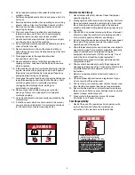
DANGER:


This machine was built to be operated according to the rules for safe operation in this manual. As with 

any type of power equipment, carelessness or error on the part of the operator can result in serious injury. This 
machine is capable of amputating hands and feet and throwing objects. Failure to observe the following safety 
instructions could result in serious injury or death.

Training

1.

Read, understand, and follow all instructions on the 
machine and in the manual(s) before attempting to 
assemble and operate. Keep this manual in a safe place 
for future and regular reference and for ordering 
replacement parts. 

2.

Be familiar with all controls and their proper operation. 
Know how to stop the machine and disengage them 
quickly.

3.

Never allow children under 14 years old to operate this 
machine. Children 14 years old and over should read and 
understand the operation instructions and safety rules in 
this manual and should be trained and supervised by a 
parent. 

4.

Never allow adults to operate this machine without 
proper instruction. 

5.

Thrown objects can cause serious personal injury. Plan 
your snow throwing pattern to avoid discharge of material 
toward roads, bystanders and the like. 

6.

Keep bystanders, helpers, pets and children at least 75 
feet from the machine while it is in operation. Stop 
machine if anyone enters the area.

7.

Exercise caution to avoid slipping or falling, especially 
when operating in reverse.

Preparation

1.

Thoroughly inspect the area where the equipment is to 
be used. Remove all door mats, newspapers, sleds, 
boards, wires and other foreign objects which could be 
tripped over or thrown by the auger/impeller. 

2.

Always wear safety glasses or eye shields during 
operation and while performing an adjustment or repair to 
protect your eyes. Thrown objects which ricochet can 
cause serious injury to the eyes.

3.

Do not operate without wearing adequate winter outer 
garments. Do not wear jewelry, long scarves or other 
loose clothing which could become entangled in moving 
parts. Wear footwear which will improve footing on 
slippery surfaces. 

4.

Use a grounded extension cord and receptacle for all 
units with electric start engines. 

5.

Adjust collector housing height to clear gravel or crushed 
rock surfaces. 

6.

Disengage the control handle before starting the engine. 

7.

Never attempt to make any adjustments while engine is 
running, except where specifically recommended in the 

operator’s manual.

8.

Let engine and machine adjust to outdoor temperature 
before starting to clear snow. 

9.

To avoid personal injury or property damage use extreme 
care in handling gasoline. Gasoline is extremely 
flammable and the vapors are explosive. Serious 
personal injury can occur when gasoline is spilled on 
yourself or your clothes which can ignite. Wash your skin 
and change clothes immediately.

a.

Use only an approved gasoline container.

b.

Extinguish all cigarettes, cigars, pipes and other 
sources of ignition.

c.

Never fuel machine indoors. 

d.

Never remove gas cap or add fuel while the 
engine is hot or running. 

e.

Allow engine to cool at least two minutes before 
refueling.

f.

Never over fill fuel tank. Fill tank to no more than 
½ inch below bottom of filler neck to provide space 
for fuel expansion.

g.

Replace gasoline cap and tighten securely.

h.

If gasoline is spilled, wipe it off the engine and 
equipment. Move machine to another area. Wait 5 
minutes before starting the engine.

i.

Never store the machine or fuel container inside 
where there is an open flame, spark or pilot light 
(e.g. furnace, water heater, space heater, clothes 
dryer etc.). 

j.

Allow machine to cool at least 5 minutes before 
storing.

Operation


1.

Do not put hands or feet near rotating parts, in the auger 
housing or discharge chute. Contact with the rotating 
parts can amputate hands and feet. 

2.

The auger control handle is a safety device. Never 
bypass its operation. Doing so, makes the machine 
unsafe and may cause personal injury. 

3.

The control handle must operate easily in both directions 
and automatically return to the disengaged position when 
released. 

4.

Never operate with a missing or damaged discharge 
chute. Keep all safety devices in place and working.

5.

Never run an engine indoors or in a poorly ventilated 
area. Engine exhaust contains carbon monoxide, an 
odorless and deadly gas. 

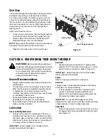
Summary of Contents for OGST-2806

Page 1: ...ower PRINTED IN U S A Operator s Manual FORM NO OGST 2806 6 2005 MTD Products Ltd P O BOX 1386 KITCHENER ONTARIO N2G 4J1 33 Model Shown IMPORTANT Read safety rules and instructions carefully before op...

Page 2: ...gine manufacturer s Owner s Operator s Manual packed separately with your unit for more information CALLING CUSTOMER SUPPORT Please do NOT return the unit to the retailer from which it was purchased w...

Page 3: ...g an adjustment or repair to protect your eyes Thrown objects which ricochet can cause serious injury to the eyes 3 Do not operate without wearing adequate winter outer garments Do not wear jewelry lo...

Page 4: ...operation regularly 2 Disengage the control handle and stop engine Wait until the auger impeller come to a complete stop Disconnect the spark plug wire and ground against the engine to prevent uninten...

Page 5: ...e observed from the operating position Assembling Handle Remove the lower plastic wing nut cupped washer and carriage bolt from each side of the lower handle See Figure 2 Raise the upper handle assemb...

Page 6: ...ure 4 With the hex nuts loosened on the lower chute crank bracket see Figure 5 adjust the bracket so that the spiral on the chute crank fully engages the teeth on the chute assembly Tighten the nuts o...

Page 7: ...ontrol Check the adjustment of the auger control as follows When the auger control is released and in the disengaged up position the cable should have very little slack but should NOT be tight See Fig...

Page 8: ...e control the operator can release the auger control on the left handle and the augers will remain engaged Release the drive control to stop the augers and wheel drive the auger control must also be r...

Page 9: ...f the chute assembly Move the chute tilt control forward to decrease the distance toward the rear to increase Wheel Steering Controls The left and right wheel steering controls are located on the unde...

Page 10: ...ers move choke immediately to FULL and then gradually to OFF When disconnecting the power cord always unplug from the three prong receptacle first and then from the snow thrower Recoil Starter Rotate...

Page 11: ...trol if engaged Operating Tips NOTE Allow the engine to warm up for a few minutes The engine will not develop full power until it reaches operating temperature If possible remove snow immediately afte...

Page 12: ...d check if there is clearance between friction wheel and drive plate in all positions of the shift lever See Figure 14 With the traction control lever engaged check if the friction wheel solidly conta...

Page 13: ...ive and Shifting Mechanism At least once a season or after every 25 hours of operation remove rear cover Lubricate any chains sprockets gears bearings shafts and the shifting mechanism at least once a...

Page 14: ...utomotive grease The cams can be accessed beneath the handle panel See Figure 18 Figure 18 Friction Wheel Rubber Follow the instructions below to check the condition of the friction wheel rubber every...

Page 15: ...the housing Tighten securely Replacing Belts Disconnect the chute crank assembly at the discharge chute end by removing the hairpin clip and the flat washer Remove the plastic belt cover located near...

Page 16: ...belt from the engine pulley and bottom drive pulley Replace belt and reassemble in reverse order Figure 22 Figure 23 Reassemble the two halves of the unit hooking the lower portion of the auger housi...

Page 17: ...er to the friction wheel assembly tightening the four screws in rotation and with equal force SeeFigure 25 It is important to assemble the rubber on the friction wheel symmetrically for proper functio...

Page 18: ...running on CHOKE 2 Blocked fuel line or stale fuel 3 Water or dirt in fuel system 4 Carburetor out of adjustment 1 Move choke lever to OFF position 2 Clean fuel line and fill tank with clean fresh gas...

Page 19: ...on wheels Full Ninety Day Warranty on Battery For ninety 90 days from the date of retail purchase if any battery included with this unit proves defective in material or workmanship and our testing det...

Page 20: ...assembly instructions in the owners manual for correct adjustment Consultez les instructions concernant le r glage correct dans la notice d utilisation Flats 6 parallel to rear when installing engage...

Page 21: ...de la c ble 42 731 0903D Lower Chute Remote Tilt Partie inf rieur noir de la bouche d vacuation 44 736 0159 Flat Washer 349 ID x 879 OD x 063 Rondelle plate 0 349 DI x 0 879 DE x 0 063 46 746 0902 Chu...

Page 22: ...63 83 28 30 33 in po 45 in po 28 26 100 100 26 24 24 24 28 28 26 87 87 84 85 90 26 28 92 When rebuilding gear box fill one housing half completely with grease 838 0168 Pour remonter la bo te d engrena...

Page 23: ...n 32 736 03046A Flat Washer 1 010 x 1 88 x 060 Rondelle plate 1 010 x 1 88 x 0 06 33 05244A Bearing Housing Bo tier de roulement 34 711 0640 Belt Keeper Studs 3 8 16 x 2 75 Goujons du protecteur de la...

Page 24: ...gement de la goulotte 104 710 0458 Carriage Bolt 5 16 18 x 1 75 Boulon ordinaire 5 16 18 x 1 75 31A 8012 4 29 05 24 AUGER HOUSING COMPONENTS COMPOSANTS DU LOGEMENT DES TARI RES SIZE TAILLE DESCRIPTION...

Page 25: ...D x 120 Rondelle plate 0 344 DI x 0 75 DE x 0 120 11 738 0281 Shoulder Scr 625 Dia x 170 Vis paulement dia 0 625 x 0 170 po 12 747 0980 Auger Idler Rod Tige de tension de la tari re 13 756 0178 Flat I...

Page 26: ...16 15 63 9 16 16 64 16 72 3 52 52 32 24 42 1 67 6 16 16 73 60 51 37 87 8 61 52 22 20 21 34 68 79 47 61 30 54 69 33 52 87 55 8 46 59 53 11 20 21 4 74 71 65 57 26 50 47 86 17 14 50 26 62 49 25 6148 12...

Page 27: ...ex Nut 3 8 16 crou hex 3 8 16 31 712 3010 Hex Nut 5 16 18 hd Gr 5 crou hexagonal 5 16 18 Qual 5 32 713 0284 41 Chain 1 2 pitch x 36 links Endless Cha ne no 41 pas de 1 2 po x 36 maillons 33 713 0286 4...

Page 28: ...u 0 995 x 14 10 Lg 30 po 33 po 738 1165A Axle 995 x 12 6 Lg 28 Essieu 0 995 x 12 0 Lg 28 po 738 1166A Axle 995 x 20 4 Lg 45 Essieu 0 995 x 20 4 Lg 45 po 81 See chart below Voir le tableau ci dessous 8...

Page 29: ...1 4 x 1 50 po de lg 18 732 0303 Brake Return Ext Spring 3 18 Lg Ressort d alimentation 3 8 x 3 18 20 736 0217 Lockwasher Heavy 3 8 ID Rondelle frein 3 8 DI 21 736 0242 Cupped Washer 340 ID x 872 OD x...

Page 30: ...cut out Ouvertures pour goulotte inclinable Attache to loose hangine wire under fuel tank on engine attacher au fil m tallique qui pend dessous le r servoir du moteur Ground wire Fil de terre STYLE 6...

Page 31: ...0 20 712 3010 Hex Nut 5 16 18 hd Gr 5 crou hexagonal 5 16 18 Qual 5 21 725 0586 Lamp Housing Logement du phare 22 725 1300 Sealed Beam 18 Watt CGE 4414 1 Phare scelle CGE no 4414 1 18 watt 23 736 0119...

Page 32: ...lames les sacs herbe les roues des tondeuses les si ges les pneus et les pi ces de l embrayage roues de frottement Garantie compl te de quatre vingt dix jours sur la batterie MTD s engage remplacer gr...

Page 33: ...happement est bouch 1 Branchez et serrez le fil de la bougie 2 D gagez la glace et la neige du chapeau Assurez vous de la propret du trou d a ration 3 Adressez vous une station technique Moteur surcha...

Page 34: ...z plac un morceau de plastique sous le bouchon d essence plus t t enlevez le maintenant Figure 26 CHAPITRE 8 INSTRUCTIONS DE REMISAGE AVERTISSEMENT N entreposez jamais le moteur avec du carburant dans...

Page 35: ...frottement d s l apparition de signes d usure ou si vous apercevez des fendillements Videz l essence de la souffleuse ou placez un morceau de plastique sous le bouchon d essence Basculez la souffleus...

Page 36: ...de la tari re Retirez les boulons et rondelles frein du haut qui maintiennent l habitacle de la tari re sur le ch ssis Utilisez une cl de 9 16es de po Voir la Figure 19 S parez le bo tier de la tari r...

Page 37: ...structions la page 18 Courroies d entra nement Suivez les instructions ci dessous pour v rifier l tat des courroies d entra nement toutes les 50 heures d utilisation D montez le couvre courroie en pla...

Page 38: ...ission hex avec la graisse 6 en 1 num ro de pi ce 737 0170 au moins une fois par saison ou toutes les 25 heures d utilisation Voir la Figure 14 Bo te de l engrenage La bo te de l engrenage vis sans fi...

Page 39: ...u interm diaire si la zone d gager est irr guli re Sur une surface recouverte de gravier placez toujours les patins la position la plus haute Voir la Figure 15 Proc dez comme suit pour ajuster les pat...

Page 40: ...que la virole soit align e avec le trou du haut du levier de vitesses Voir la Figure 13 Installez la virole du c t gauche de la souffleuse dans le trou du haut du levier de vitesses Maintenez le tout...

Page 41: ...pr s de les commandes D placez celles ci plusieurs fois DEMBRAYAGE DE L ENTRA NEMENT DES ROUES Quand le moteur tourne presque plein r gime placez le levier de vitesses l une des positions de MARCHE A...

Page 42: ...es en installer une par un lectricien qualifi Si vous avez une prise de courant trois trous reli s la terre proc dez comme suit Branchez le fil lectrique dans le commutateur sur le moteur Branchez l a...

Page 43: ...s ou b timents Levier de vitesses Il se trouve au milieu du tableau de bord et sert choisir la vitesse et la direction de d placement Il peut tre plac l une quelconque de huit positions Goulotte d jec...

Page 44: ...re AVERTISSEMENT La pression maximale des pneus ne doit jamais d passer 30 lb po2 Maintenez toujours une pression gale dans tous les pneus Une pression excessive sup rieure 30 lb po2 lors du montage d...

Page 45: ...d vissez le c ble d un tour complet V rifiez l ajustement Resserrez le contre crou sur le c ble quand l ajustement est satisfaisant REMARQUE Pour plus de d tails consultez la section Commande de l ent...

Page 46: ...support de la manivelle de la goulotte tant desser s et ajustez celui ci voir la Figure 5 de mani re que la partie h lico dale de la manivelle s engr ne bien avec les dents de la goulotte Serrez les...

Page 47: ...age du guidon Enlevez les deux crous oreilles en plastique les deux rondelles creuse et les deux boulons ordinaires inf rieurs de chaque c t du guidon inf rieur Voir la Figure 2 Relevez le guidon sup...

Page 48: ...oncernant l limination des d chets et liquides qui risquent de nuire la nature et l environnement 9 Laissez la machine fonctionner pendant quelques minutes pour liminer la neige de la tari re et viter...

Page 49: ...ravaillant sur une pente 10 Pr voyez de travailler en vitant de projeter la neige vers des fen tres murs voitures etc car les d bris peuvent ricocher et causer des blessures graves ou des d g ts mat r...

Page 50: ...bien le fonctionnement de la machine de s en servir 5 Les objets projet s par la machine peuvent causer des blessures graves Pr voyez de travailler en vitant de projeter la neige vers la route des sp...

Page 51: ...service Pour plus de renseignements consultez votre notice d utilisation du moteur empaquet s par ment avec votre souffleuse SERVICE APR S VENTE Veuillez retourner la machine au d taillant qui vous l...

Page 52: ...isation FORM NO OGST 2806 6 2005 MTD Products Ltd P O BOX 1386 KITCHENER ONTARIO N2G 4J1 IMPRIM AUX TATS UNIS Mod le de 33 po illustr IMPORTANT Lisez attentivement les r gles de s curit et les instruc...

Reviews: