background image

2.  Inspection and adjustment

22

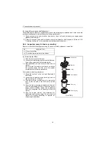
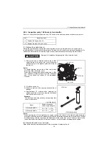
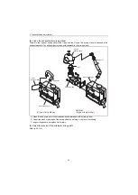
(4) Adjust the tension of the alternator drive belt

When there is not enough tension in the V-belt, it will
slip and the cooling water pump will fail to supply
cooling water. Engine over-heating and the seizure will
occur.
When there is too much tension in the V-belt, the belt
will become damaged more quickly and the bearing of
the cooling water pump may be damaged.
Check and adjust the V-belt tension (deflection) in the
following manner.

[Notice]

Be especially careful not to splash engine oil on the

V-belt, because it will cause slipping, stretching and

aging of the belt.

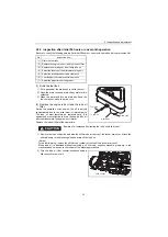
1) Remove the belt cover. Check the tension of the V-

belt by pressing down on the middle of the belt

with your finger [approx. 98N(10kgf)].

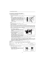
The specified deflection should be as follows.

• "New V-belt" refers to a V-belt which has been used less than 5 minutes on a running engine.
• "Used V-belt" refers to a V-belt which has been used on a running engine for 5 minutes or more.

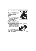
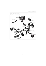
2) If necessary, adjust the V-belt tension (deflection).

To adjust the V-belt tension, loosen the set bolt for

the belt adjuster and move the alternator to tighten
the V-belt.

3) Visually check the V-belt for cracks, oiliness or

wear.  If any, replace the V-belt with new one.

[Notice]

When the V-belt will be replaced with new one,

loosen the set bolt, move the alternator and also

loosen the V-pulley set bolts for the cooling water

pump. Remove the V-belt.
After replacing with a new V-belt and adjusting the

tension, run the engine for 5 minutes and readjust the

deflection to the value in the table above.

For used V-belt

8-10 mm (0.315-0.393 inches)

For new V-belt

6-8 mm (0.236-0.315 inches)

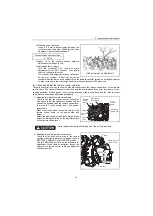
Alternator

Bracket

Belt adjuster

(3YM30)

Set bolt

V-belt

Summary of Contents for 3YM20

Page 1: ...M9961 03E100 ...

Page 2: ...9961 03E100 History of Revision Manual Name Service Manual for Marine Diesel Engine Engine Model 3YM30 3YM20 Number of revision Date of revision Reason for correction Outline of correction Correction item No page Corrected by New edition March 2004 ...

Page 3: ...y of the ship s piping and propeller and not just the engine itself To get maximum performance from this engine you should completely understand its functions construction and capabilities as well as proper use and servicing Use this manual as a handy reference in daily inspection and maintenance and as a text for engineering guidance Model 3YM30 has been used for the illustrations in this service...

Page 4: ...rs or one month operation 20 2 2 3 Inspection every 50 hours or monthly 25 2 2 4 Inspection every 100 hours or two months 30 2 2 5 Inspection every 250 hours or one year 31 2 2 6 Inspection every 1 000 hours or four years 37 2 3 Adjusting the no load maximum or minimum speed 44 2 4 Sensor Inspection 44 2 4 1 Oil pressure switch 44 2 4 2 Thermo switch 44 2 5 Thermostat inspection 45 2 6 Adjusting o...

Page 5: ...linder bore measurement 106 5 2 Cylinder head 107 5 2 1 Inspecting the cylinder head 108 5 2 2 Valve seat correction procedure 109 5 2 3 Intake exhaust valves valve guides 110 5 2 4 Valve springs 112 5 2 5 Assembling the cylinder head 113 5 2 6 Measuring top clearance 114 5 2 7 Intake and exhaust rocker arms 114 5 2 8 Adjustment of valve clearance 115 5 3 Piston and piston pins 116 5 3 1 Piston 11...

Page 6: ...ting of fuel injection pump 141 6 1 8 Major faults and troubleshooting 141 6 2 Fuel feed pump 144 6 2 1 Construction of fuel feed pump 144 6 2 2 Fuel feed pump specifications 144 6 2 3 Disassembly and reassembly of fuel feed pump 145 6 2 4 Fuel feed pump inspection 145 6 3 Fuel filter 147 6 3 1 Fuel filter specifications 147 6 3 2 Fuel filter inspection 147 6 4 Fuel tank 148 7 Intake and exhaust s...

Page 7: ...sembly 163 9 3 4 Fresh water pump inspection 163 9 4 Heat exchanger 165 9 4 1 Heat exchanger construction 165 9 4 2 Disassembly and reassembly of the heat exchanger 165 9 4 3 Heat exchanger inspection 165 9 5 Pressure cap and coolant recovery tank 166 9 5 1 Pressure cap construction 166 9 5 2 Pressure cap pressure control 166 9 5 3 Pressure cap inspection 166 9 5 4 Replacing filler neck 167 9 5 5 ...

Page 8: ...rical system 183 12 1 Electrical system 183 12 1 1 Wiring diagram 184 12 2 Battery 185 12 3 Starting motor 186 12 3 1 Specifications 186 12 3 2 Characteristics 186 12 3 3 Structure 187 12 3 4 Wiring diameter of a starting motor 188 12 4 Alternator standard 12V 60A 189 12 4 1 Specifications 189 12 4 2 Structure 190 12 4 3 Wiring diagram 191 12 4 4 Standard output characteristics 191 12 4 5 Inspecti...

Page 9: ...ce standards 201 13 1 Engine tuning 201 13 2 Engine body 202 13 2 1 Cylinder head 202 13 2 2 Camshaft and gear train 203 13 2 3 Cylinder block 204 13 3 Lubricating oil system Trochoid pump 207 14 Tightening torque for bolts and nuts 208 14 1 Main bolt and nut 208 14 2 Standard bolts and nuts without lube oil 208 ...

Page 10: ...nce in the manual Sufficient consideration for safety is required in addition to the matters marked Especially for safety precautions in a repair or maintenance job not described in this manual receive instructions from a knowledgeable leader Safety marks used in this manual and their meanings are as follows DANGER indicates an imminent hazardous situation which if not avoided WILL result in death...

Page 11: ...ll type accidents Clean orderly arranged place No dust mud oil or parts should be left on the floor surface Failure to Observe An unexpected accident may be caused Bright Safely Illuminated Area The work area should be well lit or illuminated in a safe manner For work in enclosed or dark areas a drop cord should be utilized The drop cord must have a wire cage to prevent bulb breakage and possible ...

Page 12: ...ap as an attaching device Do not use rope serious injury may result To hold or support an engine secure the engine to a support stand test bed or test cart designed to carry the weight of the engine Do not overload this device serious injury may result Never run an engine without being properly secured to an engine support stand test bed or test cart serious injury may result Appropriate Tools Alw...

Page 13: ...of ignition away Explosion may occur causing severe personal injury Battery Electrolyte Batteries contain sulfuric acid Do NOT allow it to come in contact with clothing skin and or eyes severe burns will result 7 WASTE MANAGEMENT Observe the following instructions with regard to hazardous waste disposal Negligence of these will have a serious impact on environmental pollution concerns 1 Waste flui...

Page 14: ...ng jewelry ties or tools may become entangled causing damage to the engine and or severe personal injury Preventing burns from scalding 1 Never open the radiator filler cap shortly after shutting the engine down Steam and hot water will spurt out and seriously burn you Allow the engine to cool down before attempt to open the filler cap 2 Securely tighten the filler cap after checking the radiator ...

Page 15: ...ed check the part installed state deformation damage roughening surface defect etc Arrange the removed parts orderly with clear distinction between those to be replaced and those to be used again Parts to be used again shall be washed and cleaned sufficiently Select especially clean locations and use clean tools for disassembly of hydraulic units such as the fuel injection pump 5 Precautions for I...

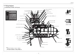
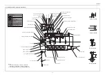
Page 16: ... silencer Intake manifold Fuel filter Fuel injection pump Oil filter cap Dipstick Oil filter cap Fuel feed pump Lubricating oil filter Marine gear Sea water pump Alternator V belt Shift lever Starter motor Exhaust manifold Coolant tank Heat exchanger Engine name plate on the rocker arm cover Fresh water filler cap Non Operating Side Cover ...

Page 17: ...eg b T D C FID 16 1 FIC Air 18 1 FID 22 1 FIC Air 24 1 Fuel injection opening pressure MPa kgf cm2 11 8 0 98 0 120 10 0 12 3 0 98 0 125 10 0 Main power take off At Flywheel side Direction of rotation Crankshaft Counter clockwise viewed from stern Propeller shaft Ahead Clockwise viewed from stern Cooling system Fresh water cooling with heat exchanger Lubrication system Complete enclosed forced lubr...

Page 18: ...l temperature 25 C at the inlet of the fuel injection pump ISO 3046 1 Fuel temperature 40 C at the inlet of the fuel injection pump ISO 8665 4 The Total oil quantity includes oil in oil pan and oil in channels coolers and filter 5 The effective amount of oil shows the difference in maximum scale of the dipstick and minimum scale ...

Page 19: ... deposited on the bottom Pump up only the clean fuel 3 Fuel tank Be sure to attach a drain cock precipitation trap and primary strainer to the fuel tank as shown illustration right 1 3 2 Lubricating oil IMPORTANT Use of other than the specified engine oil may cause inner parts seizure or early wear leading to shorten the engine service life 1 Selection of engine lube oil Use the following engine o...

Page 20: ...nd be sure to add the Long Life Coolant Antifreeze LLC in order to prevent rust built up and freezing If there is any doubt over the water quality distilled water or pre mixed coolant should be used The coolants antifreezes which are good performance for example are shown below TEXACO LONG LIFE COOLANT ANTIFREEZE both standard and pre mixed Product codes 7997 and 7998 HAVOLINE EXTENDED LIFE ANTIFR...

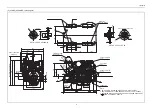
Page 21: ...ARIN 8 MOUNTING BLOCKS ID 75 MOUNTING BLOCKS ID 100 P C 78 P C 82 5 100 35 50 0 025 0 63 5 0 046 0 4 17 42 12 x 30 355 182 5 7 178 5 178 5 174 206 12 DIRECTION OF ROTATION 4 M8 7 DETAIL OF PULLEY B 6 715 5 291 LO FILTER 97 279 5 48 FRESH WATER DRAIN 8 B FUEL OVERFLOW 8 0 FUEL INLET 8 3 SEAWATER INLET 17 3 Crankshaft center NOTE 1 DWG SHOWS MOUNTING BLOCKS AT ORIGINAL HEIGHT 2 ENGINE WEIGHT WILL CO...

Page 22: ...TE 1 DWG SHOWS MOUNTING BLOCKS AT ORIGINAL HEIGHT 2 ENGINE WEIGHT WILL COMPRESS BLOCKS BY 4 5 mm APPROX 3 MOUNTING BLOCKS ARE EQUIPPED FOR STANDARD ACCESSORY 4 SHOWS CENTER OF GRAVITY MOUNTING BLOCKS ID 100 U MIXING ELBOW OPTIONAL DETAIL OF PULLEY A DIRECTION OF ROTATION 311 181 5 557 P C 82 5 42 63 5 0 046 0 2 17 12 MAX DIA OF PROP 406 16 INCH SEA WATER DRAIN 8 FRESH WATER DRAIN 8 FUEL OVERFLOW 8...

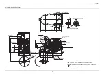
Page 23: ...AWATER DRAIN 8 ADJUSTABLE 80A ALTERNATOR OPTIONAL FRESH WATER DRAIN 8 FUEL OVERFLOW 8 0 SEAWATER INLET 17 3 A LO FILTER FUEL INLET 8 3 U MIXING ELBOW OPTIONAL SEAWATER DRAIN PLUG MOUNTING BLOCKS ID 75 4 17 12 12x30 MOUNTING BLOCKS ID 100 A DETAIL OF PULLEY B 4 M8 DIRECTION OF ROTATION DETAIL OF COUPLING A 4 10 5 178 5 NOTE 1 DWG SHOWS MOUNTING BLOCKS AT ORIGINAL HEIGHT 2 ENGINE WEIGHT WILL COMPRES...

Page 24: ...3 248 274 31 10 SEAWATER DRAIN 8 80A ALTERNATOR OPTIONAL FRESH WATER DRAIN 8 FUEL OVERFLOW SEAWATER INLET A LO FILTER FUEL INLET 8 0 17 3 8 3 U MIXING ELBOW OPTIONAL AHEAD MOUNTING BLOCK ID 230 12 12 x 30 MOUNTING BLOCKS ID 100 DETAIL OF PULLEY A 4 M8 DIRECTION OF ROTATION 2 17 ASTERN NOTE 1 DWG SHOWS MOUNTING BLOCKS AT ORIGINAL HEIGHT 2 ENGINE WEIGHT WILL COMPRESS BLOCKS BY 4 5 mm APPROX 3 MOUNTI...

Page 25: ...To cam shaft 8 5 8 16 5 8 9 17 17 18 Detail of part C 50 Detail of part B Detail of part D Detail of part A Screw joint Union Marks of piping Flange joint Eye joint Insertion joint Drill hole Cooling fresh water piping Cooling seawater piping Lubricating oil piping Fuel oil piping To oil pan Seawater inlet 5 x t4 5 rubber hose 7 8 x t4 5 rubber hose 7 8 x t4 5 rubber hose 7 8 x t4 5 rubber hose 4 ...

Page 26: ...5 8 16 5 8 9 17 17 18 Detail of part C 50 Detail of part B Detail of part D Detail of part A Screw joint Union Marks of piping Flange joint Eye joint Insertion joint Drill hole Cooling fresh water piping Cooling seawater piping Lubricating oil piping Fuel oil piping To oil pan Seawater inlet 5 x t4 5 rubber hose 7 8 x t4 5 rubber hose 7 8 x t4 5 rubber hose 7 8 x t4 5 rubber hose 4 76 x t0 7 steel...

Page 27: ...B EPA and ARB label Note Emission Control is accomplished through Engine Modification EM Design The tamper resistance device is installed with EPA ARB certified 3YM30 series engines to prevent illegal change of fuel injection volume and high idling speed Fuel injection volume cap type High idling speed cap type Engine family name as assigned by EPA ARB identifying engine family group 4YDXM1 64D3N ...

Page 28: ... CD 3 Do not remove the caps restricting injection quantity and engine speed 4 Perform maintenance without fail Note Inspections to be carried out by the user and by the maker are divided and set down in the List of Periodic Inspection on the operation manual and should be checked carefully EPA allows to apply the maintenance schedule for the emission related parts as follows Engine Power Tier Mod...

Page 29: ...c Inspections on the operation manual and use the table below to carry out inspections based on operation hours or time in years Whichever comes first is the guarantee period The specific emissions related parts are a Fuel injection nozzle b Fuel injection pump Parts Power Rating For fuel nozzle fuel pump kW 19 1500 hours or 2 years 19 kW 37 3000 hours or 5 years ...

Page 30: ... Drain the fuel tank Drain the fuel filter Replace the fuel filter Å Check the injection timing z Check the injection spray condition z 1 Lubricating system Check the lube oil level Crankcase Marine gear Replace the lube oil Crankcase Å Å Marine gear Å Å Sail drive Å Å Replace the engine lube oil filter Å Å Cooling system Seawater outlet During operation Check cooling water level Check the impelle...

Page 31: ...very 250 hrs or one year 2 Every 1000 hrs or 4 years Electrical system Check the alarm lamps devices Check the electrolyte level in the battery Adjust the tension of the alternator driving belt Å Check the wiring connectors Cylinder head etc Check for leakage of water and oil After starting Retighten all major nuts and bolts z Adjust intake exhaust valve clearance z Remote control system etc Check...

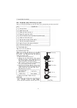
Page 32: ...appropriate viscosity No cooling water or diesel fuel shall be mixed Standard The level shall be between the upper and lower limit lines on the dipstick b If the remaining engine oil level is low fill the oil pan with the specified engine oil to the specified level through the filler port NOTICE The engine oil should not be overfilled to exceed the upper limit line If engine oil is overfilled the ...

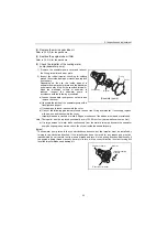
Page 33: ...ightened loosely steam can spurt out during operation 1 Checking cooling water volume Check the cooling water level in the coolant recovery tank If the water level is close to the LOW mark open the coolant recovery tank cap and replenish the coolant recovery tank with clean soft water to the FULL mark Standard The water level of the coolant recovery tank shall be between the upper and lower limit ...

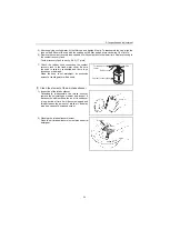
Page 34: ...the engine check the leakage of cooling water and seawater from cooling water system Also check the leakage of lube oil and fuel 8 Check adjust the remote control operation Make sure that the accelerator of a boat can be operated smoothly before starting the engine If it feels heavy to manipulate lubricate the accelerator cable joints and pivots Adjust the accelerator cable if there is a dislocati...

Page 35: ...lter at the same time Beware of oil splashes if extracting the Lube oil while it is hot 1 Remove the lube oil dipstick and also the oil filler cap at the top of the rocker arm cover Attach the oil drain pump to the dipstick guide and drain off the lube oil Notice For easier draining remove the oil filler cap yellow at the top of the rocker arm cover When lube oil is absorbed without removing a oil...

Page 36: ...nder block decreases with the function of the diaphragm in the rocker arm cover Therefore measure the lube oil level about 10 minutes later after stopping the engine or after removing the oil filler cap Note The yellow label shown right is attached on the dipstick 3 Replace the marine gear lube oil During initial operation the oil is quickly contaminated due to the initial wear of internal parts T...

Page 37: ... deflection should be as follows New V belt refers to a V belt which has been used less than 5 minutes on a running engine Used V belt refers to a V belt which has been used on a running engine for 5 minutes or more 2 If necessary adjust the V belt tension deflection To adjust the V belt tension loosen the set bolt for the belt adjuster and move the alternator to tighten the V belt 3 Visually chec...

Page 38: ...Use it as the data for estimating the wear state d Adjusting other cylinders Turn the crankshaft 240 and make adjustment for the No 3 cylinder Then adjust the No 2 cylinder in this order The cylinder to be adjusted first does not have to be the No 1 cylinder Select and adjust the cylinder where the piston is the nearest to the top dead center after turning and make adjustment for other cylinders i...

Page 39: ... remote control cable must be checked and adjusted periodically 1 Adjusting the throttle remote control cable Check to see that the control lever on the engine side moves to the high speed stop position and low speed stop position when the remote control lever is moved to H high speed and L low speed respectively When there is deviation loosen the clamp for the remote control cable on the engine s...

Page 40: ... reassembly be sure to vent air from the fuel system If air is in the fuel system fuel cannot reach the fuel injection pump Vent the air in the system according to the following procedures Fuel system air bleeding procedures 1 Check the fuel level in the fuel tank Replenish if Insufficient 2 Loosen the air bleeding bolt at the top of the fuel filter by turning it 2 or 3 times 3 Feed fuel with the ...

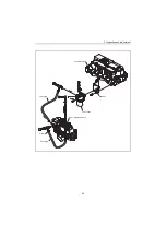
Page 41: ...2 Inspection and adjustment 26 Cylinder head Bracket Fuel filter Fuel pipe Fuel injection pump Clamp Fuel pipe ...

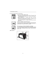
Page 42: ...o connect the Negative battery cable back onto the battery LAST Proper ventilation of the battery area Keep the area around the battery well ventilated paying attention to keep away any fire source During operation or charging hydrogen gas is generated from the battery and can be easily ignited Do not come in contact with battery electrolyte Pay sufficient attention to avoid your eyes or skin from...

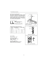
Page 43: ...ter daily use if letting the machine unit leave in the place that the ambient temperature could drop at 15 C or less And store the battery in a warm place until the next use the unit to start the engine easily at low ambient temperature 2 Battery charge Use a battery tester or hydrometer and check the battery condition If the battery is discharged recharge it a Measurement with a battery tester Wh...

Page 44: ...fic gravity and remaining battery charge 3 Terminals Clean if corroded or soiled 4 Mounting bracket Repair or replace it if corroded Retighten if loosened 5 Battery appearance Replace the battery if cracked or deformed Clean with fresh water if contaminated Specific gravity 20 C Dischargedquantity of electricity Remaining charge 1 28 0 100 1 26 10 90 1 24 20 80 1 23 25 75 Float Battery charge meas...

Page 45: ...e rubber of the diaphragm cracked 2 Fill with new lube oil 3 Perform a trial run of the engine and check the oil leakage 4 Approximately 10 minutes after stopping the engine check the oil level by using the oil dipstick Add oil if the level is too low Standard The level shall be between the upper and lower limit lines on the dipstick Notice When checking the oil level right after the engine runnin...

Page 46: ...he new fuel filter 4 Install the new fuel filter manually turning until it comes into contact with the mounting surface and tighten it further to one turn using a filter wrench Tightening torque 20 24N m 5 Bleed the fuel system Refer to 2 2 3 1 IMPORTANT Be sure to use genuine Yanmar part super fine mesh filter Otherwise it results in engine damage uneven engine performance and shorten engine life...

Page 47: ... cover d If any of the following problems are found take out the O ring and impeller If necessary replace with new one and reassemble the cover Impeller blades are cracked or nicked Edges or surfaces of the blades are marred or scratched Note The impeller must be replaced periodically every 1000 hrs or four years whichever comes first e If a large amount of water leaks continuously from the water ...

Page 48: ...rties of the agent will degenerate 1 Open the two cocks for fresh water and extract the fresh water Note One drain cock is behind the belt cover Remove the belt cover and open the cock 2 Close the two cocks for fresh water 3 Remove the filler cap of the fresh water cooler by turning the cap counterclockwise 1 3 of a turn 4 Pour cooling water slowly into the coolant tank so that air bubbles do not ...

Page 49: ...r Be sure the hose is securely connected and there is no looseness or damage When the hose is not watertight an excessive amount of cooling water will be used 7 Clean the element of the air intake silencer 1 Inspection of the intake silencer Occasionally disassemble the intake silencer remove the polyurethane element and inspect it Because the element filters the air if it is used over a long peri...

Page 50: ...lbow 1 Clean dirt and scale out of the air pass and seawater pass of the mixing elbow 2 Repair the crack or damage of the mixing elbow by welding or replace if necessary 3 Inspect the gasket and replace if necessary 9 Adjust the tension of the alternator driving belt Refer to 2 2 2 4 U type Mixing elbow L type Mixing elbow L type mixing elbow Optional L type mixing elbow Seawater Seawater Heat exc...

Page 51: ... looseness 0 20 10 30 40 GLOW B OFF ON START STOP 50 Battery switch Battery Alternator Fitting to marine gear Neutral safety switch B type panel Extension wire harness To earth bolt Starting motor Stop solenoid To lube switch and fresh water switch Safety relay Glow relay Glow connector Glow plug Magnet relay ...

Page 52: ...the crankshaft clockwise and stop turning it at the same time when the fuel comes out 7 Read the timing scale on the flywheel from the hole on the flywheel housing It is standard fuel injection timing if the timing mark position meets the fuel injection timing of the below table 8 Repeat the step 5 to 7 a few times Note Injection timing check for one cylinder is generally sufficient If it is to be...

Page 53: ...above table when adjusting a new fuel nozzle of a spare part Remove carbon deposit at the nozzle hole thoroughly before measurement a Connect the fuel injection valve to the high pressure pipe of the nozzle tester b Operate the nozzle tester lever slowly and read the pressure at the moment when the fuel injection from the nozzle starts c If the measured injection pressure is lower than the standar...

Page 54: ...and adjustment 39 Informative Fuel injection valve structure Nozzle holder Pressure adjusting shim Nozzle spring Nozzle spring seat Fuel return pipe Valve stop spacer Nozzle valve Nozzle Nozzle body Nozzle case nut ...

Page 55: ...ver at a rate of once or twice a second and check no abnormal injection If normal injection as shown below cannot be obtained replace the fuel injection valve No extreme difference in angle Θ Finely atomized spray Excellent spray departure 3 Nozzle valve sliding test Wash the nozzle valve in clean fuel oil Place the nozzle body vertically and insert the nozzle into the body to about 1 3 of its len...

Page 56: ...es 4 Replace the used hose clips with new ones if necessary b Heat exchanger inspection 1 Cooler core inspection a Inspect the inside of the tubes for rust or scale buildup from seawater and clean with a wire brush if necessary NOTE Disassemble and wash when the cooling water temperature reaches 85 C b Check the joints at both ends of the tubes for looseness or damage and repair if loose Replace i...

Page 57: ...open the pressure cap while the engine is running or right after stopping because high temperature steam will be blown out Remove the cap only after the water cools down a Remove scale and rust and check the seat and seat valve etc for scratches or wear Check the spring for corrosion or settling Replace if necessary NOTE Clean the pressure cap with fresh water as it will not close completely if it...

Page 58: ... the major nuts and bolts bellow by the standard tightening torques See the table in 4 5 1 Cylinder head bolts 2 Crankshaft pulley bolts 3 Fuel injection nozzle set bolts 4 Fuel pump gear set bolts 5 Fuel injection line sleeve nut Retighten the following major bolts as requested 1 Rod bolts 2 Flywheel set bolts 3 Metal cap bolts 8 Adjust intake exhaust valve clearance Refer to 2 2 2 5 for the proc...

Page 59: ...er probes in contact with the switch terminal and cylinder block while operating the engine It is abnormal if circuit is closed 2 4 2 Thermo switch Place the thermo switch in a container filled with antifreeze or oil Heat it while measuring the fluid temperature The switch is normal if the voltameter shows continuity when the fluid temperature is 93 97 deg C Standards Unit min 1 No load maximum No...

Page 60: ...lve opening temperature is carved on the flange 2 Normally the thermostat should be inspected every 500 hours or operation but it should be inspected before this if the cooling temperature rises abnormally or white smoke is emitted for a long time after engine starting 3 Replace the thermostat every year or 2000 hours of operation whichever comes first Valve opening Temperature deg C Full open lif...

Page 61: ...lation in the engine room 2 6 2 Adjusting operation procedure 1 Supply the fuel oil lubricating oil and cooling water Note Check the levels of the lube oil and cooling water again after test running for about 10 minutes and add as required 2 Start the engine and carry out idling at a low speed 700 to 900 min 1 for a few minutes 3 Run in the engine for about five minutes at the rated speed no load ...

Page 62: ...he intake exhaust valves fuel injection nozzle and cylinder head 3 Do not raise the engine speed abruptly 3 Cruising load operation 1 Do not operate the engine at full load yet but raise the speed gradually for about 10 minutes until it reaches the rated speed 2 Make sure that exhaust gas color and temperature are normal 3 Check the instrument panel and see if the water temperature and oil pressur...

Page 63: ...he silencer air cleaner and electric parts with PVC Poly Vinyl Chloride cover to prevent water and dust from depositing or entrance 7 Select a well ventilated location without moisture and dust for storage 8 Perform recharging once a month during storage to compensate for self discharge 9 When storing an engine for long time run the engine periodically according to the following procedure because ...

Page 64: ... the engine number Mentioned in the engine label Examine the machine unit name and its number in the same way When was the engine maintained last time How much period and or time has it been used after it was maintained last time What kind of problem was there on the engine last time and what kind of maintenance was dane 3 Hear the occurrence phenomenon from the operator of the engine in detail 5W...

Page 65: ... trouble in order to save time in determining their cause Begin by checking the most easily identifiable causes of difficulty Where the cause of the difficulty is not readily apparent make a thorough examination of the system from the very beginning proceeding until the point of trouble can be determined While experience is an important factor in pinpointing engine problems careful study and under...

Page 66: ...fety valve III 4 Remove and repair or replace III 5 Return to original condition I Fuel oil supply cut off III Emergency stoppage device in operation IV Miscellaneous 1 Insufficient oil in fuel oil tank 1 Loose lube oil pressure adjustment valve 2 Clogging of lube oil filter 3 Water in fuel oil tank Relay operation triggered by low lube oil pressure 5 4 Trouble with lube oil pump 3 Leakage from lu...

Page 67: ...injected Countermeasure CYLINDER OUTPUT IS UNEVEN COUNTERMEASURE Chart 2 I 1 Bleed air I 2 Disassemble and clean I 3 Replace I 4 Repair or replace I 5 Replace I 6 Tighten firmly I 7 Disassemble and clean and repair replace 1 Air in the fuel injection pump I Faulty fuel injection pump III 1 Clean IV 1 Reduce load IV 2 Adjust quantity of oil IV 3 Clean IV 4 Clean IV 5 Reduce with new oil IV 6 Clean ...

Page 68: ...iscosity of lube oil is too high 2 Damaged holding spring of pipe 1 Not enough warp in steel plate 3 Oil leakage where there is remote control 7 Worn sliding parts of forward reverse conversion valve 8 Damaged O ring V ring in oil pressure pipe 9 Low speed valve handle slips TROUBLE WITH MARINE GEAR 6 Incorrect positioning of forward reverse conversion valve I Low clutch oil pressure clutch slips ...

Page 69: ...diment to valve needle movement 1 Faulty operation of fuel pump plunger 5 Clogging of fuel filter 6 Damaged fuel cam 7 Air in fuel injection system 8 Faulty operation of adjustment rack 9 Uneven amount of fuel to cylinders 2 Damaged fuel pump plunger 3 Damaged plunger spring 4 Inaccurate assembly of fuel injection pump III Faulty operation of governor IV Miscellaneous 3 Sticking of governor sleeve...

Page 70: ...pressure I 2 Replace I 3 Disassemble and lap I 4 Disassemble and repair II 1 Delay injection timing II 2 Adjust standard injection pressure 1 Low injection pressure 1 Early fuel injection III Excessive quantity of fuel injected each time IV Miscellaneous 1 Excessive quantity of fuel is ejected from fuel pump 4 Poor quality fuel oil KNOCKING I Faulty fuel injection valve 1 Insufficient cooling wate...

Page 71: ...n pump 3 Plunger sticks 4 Oil leakage from exhaust valve 5 Air inside pump 6 Damaged exhaust valve spring 1 Worn plunger 2 Damaged plunger spring STARTING TROUBLE I Pinion gears do not mesh II 1 Tighten II 2 Repair using sandpaper II 3 Replace II 4 Repair using sandpaper Type 500 600 II 5 Replace II 6 Undercut and repair or replace II 7 Replace II 8 Replace with thicker or shorter wire II 9 Charge...

Page 72: ...V Leakage of pressurized gas from inside cylinder 3 Worn upper part of cylinder liner 4 Worn piston ring 5 Sticking of piston ring INSUFFICIENT POWER OUTPUT I Amount of oil supply from fuel injection pump inadequate 1 Worn plunger 6 Inaccurate positioning of adjustment rack 7 Clogging of fuel filter 8 Clogging of fuel oil pipe 9 Damaged valve spring 10 Faulty supply pump 2 Sticking of plunger 3 Oi...

Page 73: ...ghten safety valve III 6 Change lube oil III 7 Add lube oil III 8 Replace 1 Cooling water temperature has risen 2 Overloading 3 Faulty lube oil temperature adjustment valve IV Lube oil temperature is too high I Abnormal noise 1 Loose flywheel installment bolt 2 Loose crank pin bearing bolt 3 Worn crank pin metal 4 Faulty gear meshing II Low fuel oil pressure 1 Loose pressure adjustment 1 Clogged l...

Page 74: ...iming is incorrect 1 The drive gear or belt connections are incorrect 2 The injection pump is incorrectly installed on the engine 3 The roller holder assembly s roller or pin is worn excessively 4 The plunger is worn excessively Repair Repair and adjust injection timing Replace the assembly Replace the distributor assembly 3 The nozzle does not operate 1 The nozzle or nozzle holder is functioning ...

Page 75: ...e delivery valve spring is broken 10 The delivery valve is not sliding properly 11 The nozzle or the nozzle holder is not functioning properly 12 The injection timing is incorrect Clean or replace Inspect and repair Inspect and repair Replace Replace the distributor assembly Replace Repair or replace Repair or replace Replace Repair or replace Inspect and then repair or replace Readjust Insufficie...

Page 76: ... is not smooth Readjust or replace Repair or replace Idling is unstable 1 The injection quantities are not uniform the delivery valve is not operating properly 2 The governor s idling adjustment is improperly adjusted 3 The plunger is worn 4 The plunger spring is broken 5 The rubber damper is worn 6 The governor lever shaft pin is worn excessively 7 The feed pump blades are not operating properly ...

Page 77: ...rmality in the engine 1 Compression pressure measurement method 1 After warming up the engine remove the fuel injection pipe and valves from the cylinder to be measured 2 Crank the engine before installing the compression gage adapter a Perform cranking with the stop handle at the stop position no injection state b See 4 2 3 2 in Chapter 4 for the compression gage and compression gage adapter 3 In...

Page 78: ...e timing Incorrect valve clearance Adjust the valve clearance See 3 5 in Chapter 3 4 Cylinder head gasket Gas leak from gasket Replace the gasket Retighten the cylinder head bolts to the specified torque See 4 2 2 12 in Chapter 4 5 Intake exhaust vale Valve seat Gas leak due to worn valve seat or foreign matter trapping Sticking valve Lap the valve seat See 4 2 6 in Chapter 4 Replace the intake ex...

Page 79: ...r and lube oil Close the seacock 2 Reassembly Sufficiently clean and inspect all parts to be assembled Coat sliding and rotating parts with new engine oil when assembling Replace all gaskets and O rings Use a liquid packing agent as necessary to prevent oil water leaks Check the oil and thrust clearances etc of parts when assembling Make sure you use the correct bolt nut washer Tighten main bolts ...

Page 80: ...owing tools are required when disassembling and reassembling the engine Please use them as instructed 4 2 1 General hand tools Name of tool Illustration Remarks Wrench Size 10 x 13 Wrench Size 12 x 14 Wrench Size 17 x 19 Wrench Size 22 x 24 Screwdriver Steel hammer Local supply ...

Page 81: ...reassembly 66 Name of tool Illustration Remarks Copper hammer Local supply Mallet Local supply Nippers Local supply Pliers Local supply Offset wrench Local supply 1 set Box spanner Local supply 1 set Scraper Local supply ...

Page 82: ... of tool Illustration Remarks Lead rod Local supply File Local supply 1 set Rod spanner for hexagon socket head screws Local supply Size 6 mm 8 mm 10 mm Stariing pliers Hole type Shaft type Local supply S 0 H4 H8 H Shaft type S Hole type ...

Page 83: ...od small end bushing insertion extraction tool Locally manufactured Intake and exhaust valve insertion extraction tool Locally manufactured Crankshaft pulley insertion tool 20 12 25 80 Piston pin extractor Extraction of piston pin Insertion of piston pin 20 22 0 6 0 3 24 0 6 0 3 80 Extraction 20 5 5 9 5 75 50 26 6 M12 x P1 25 27 0 1 0 2 20 ...

Page 84: ...llustration Remarks Lube oil filter case remover Piston ring replacer for removal installation of piston ring Valve lapping tool Rubber cap type Valve lapping powder Code No 28210 000070 Feeler gauge Pulley puller Local supply Removing the coupling ...

Page 85: ...s Press tool 1 for filler neck Press tool 2 for filler neck copper tube Stem seal insertion for inserting stem seal Tool 1 25 27 5 35 5 40 89 2 1 105 30 30 170 24 2 28 30 Tool 2 Chamfer mm d1 15 0 21 12 11 0 65 4 or more d2 d3 L1 L2 L3 L2 L1 d1 d2 L2 L1 L3 d1 d2 d3 ...

Page 86: ...e of tool Illustration Remarks Vernier calipers 0 05 mm 0 150 mm Micrometer 0 01 mm 0 25 mm 25 50 mm 50 75 mm 75 100 mm 100 125 mm 125 150 mm Cylinder gauge 0 01 mm 18 35 mm 35 60 mm 50 100 mm Thickness gauge 0 05 2 mm Torque wrench 128 N m 0 13 kgf m Nozzle tester 0 49 Mpa 0 500 kgf cm2 ...

Page 87: ...d Keeps the dial gauge firmly in position thereby permitting it to be used at various angles 4 Micrometer Measures the outer diameter of the crank shaft piston piston pin etc 5 Cylinder gauge Measure the inner diameter of the cylinder liner and rod metal 6 Vernier calipers Measures various outer diameters thicknesses and widths 7 Depth micrometer Measures sinking of valves 8 Square Measures distor...

Page 88: ... for leakage in the fresh water system 13 Battery current tester Checks density of antifreeze and charging condition of battery fluid 14 Nozzle tester Checks the shape and pressure of spray emitted from the fuel injection valve at the time of injection 15 Digital thermostat Measures temperature of various parts abcdefghijklmn abcdefghijklmn abcdefghijklmn abcdefghijklmn abcdefghijklmn abcdefghijkl...

Page 89: ...ector seal which is placed on the exterior of the revolving shaft High pressure fuel pipe clamp type Measures rotation speed without reference to revolving shaft center or the exterior of the revolving shaft 17 Circuit tester Measures the resistance voltage and continuity of the electric circuit 18 Compression gauge Measures the pressure of the compression Revolving shaft Reflection mark High pres...

Page 90: ... Solvent less type silicone base sealant applicable to high temperature areas 50 C to 250 C Three Bond TB1212 100g Silicone base non fluid type thick application possible Adhesive Three Bond TB1401 200g Prevention of loose bolts gas leakage and corrosion Torque required to loosen bolt 10 to 20 larger than tightening torque Lock tight SUPER TB1324 50g Excellent adhesive strength locks bolt semi per...

Page 91: ...eight of the solvent Mix the solvent with water Just dipping disassembled part into removes scale To shorten removal time stir remover mixture If cleaning performance drops replace remover mixture with new remover mixture Neutralize used mixture and then dispose of it To judge cleaning performance of mixture put pH test paper into mixture If test paper turns red remover mixture is still effective ...

Page 92: ... a driven coupling is mounted to the front drive coupling disassemble 10 Remove the flexible mount nut lift the engine and remove it from the engine base Leave the flexible mount attached to the engine base Disassembling an engine in a workshop 1 Drain cooling water Refer to 2 2 5 6 1 Open a seawater drain cock to drain the seawater 2 Open a drain cock on the cylinder body to drain the fresh water...

Page 93: ...the oil hole on top of the case Refer to 2 2 2 2 3 3 Removing electrical wiring Remove the wiring from the engine Refer to 2 2 4 9 4 Removing the fuel filter fuel pipe 1 Remove the fuel pipes fuel filter fuel feed pump fuel filter fuel injection pump and fuel nozzle fuel pump 2 Remove the fuel filter Cylinder head Bracket Fuel filter Fuel pipe To fuel tank Fuel injection pump Clamp Fuel pipe ...

Page 94: ...er head 6 Removing the mixing elbow 1 Remove the seawater rubber hose connecting to a heat exchanger a mixing elbow 2 Remove the mixing elbow from the exhaust manifold Intake silencer Cylinder head Intake pipe U type Mixing elbow L type Mixing elbow L type mixing elbow Optional L type mixing elbow Seawater Seawater Heat exchanger Heat exchanger Exhaust elbow Joint ...

Page 95: ...ear case and remove the alternator from the cylinder head with bracket 8 Removing the cooling water pipes seawater fresh water 1 Remove the seawater pipe seawater pump heat exchanger 2 Remove the fresh water pipe fresh water pump heat exchanger coolant tank fresh water pump Alternator Bracket Belt adjuster 3YM30 Set bolt V belt Heat exchange Cooling water pipes Mixing elbow Exhaust manifold Coolan...

Page 96: ... pump Loosen the nut on the spacer bolt and remove the seawater pump 11 Removing the starting motor Remove the starting motor from the flywheel housing 12 Removing the lube oil filter Remove the lube oil filter from the cylinder block Seawater pump Gear case Spacer bolt V belt Seawater pump Bracket Starting motor Flywheel housing Lube oil pressure switch Cylinder block Lube oil filter ...

Page 97: ...ipe by hand so that the fuel return pipe may not break 3 Remove the fuel return pipe fuel nozzle fuel pump 14 Removing the fresh water pump Remove the fresh water pump and gasket No 1 No 2 No 3 Fuel injection pipe Fuel injection pump Fuel injection nozzle Fuel return pipe Fuel injection pipe retainer Fuel injection pipe Fuel injection pipe Cap nut Cap nut Fuel return pipe Fuel return pipe Fuel inj...

Page 98: ... and pull out the fuel pump drive gear flange assembly with an extraction tool Note Don t disassemble the pump flange and the pump drive gear 2 Loosen the three 3 nuts for the fuel pump and remove the fuel injection pump and O ring from the gear case Fuel injection nozzle Cylinder head Gear case cover Fuel injection pump Pump flange Fuel pump drive gear Don t disassemble Drive gear nut Pump flange...

Page 99: ... rocker arm shaft assembly 3 Pull out the push rods 18 Removing the cylinder head 1 Loosen the cylinder head bolts with a torque wrench and remove the cylinder head 2 Remove the cylinder head gasket 19 Removing the marine gearbox Loosen the bolts for the clutch case flange and remove the gearbox assembly 20 Removing the flywheel Loosen the flywheel bolts and remove the flywheel Note Be careful not...

Page 100: ...move the crankshaft V pulley with a pulley puller 23 Removing the oil pan Remove the oil pan and spacer 24 Removing the lube oil inlet pipe Remove the lube oil inlet pipe and O ring 25 Removing the gear case Loosen the gear case cover bolts and remove the gear case cover from the gear case Bolt Washer Crankshaft V pully Gear case Oil pan Wood block Flywheel housing Oil pan Oil pan spacer Cylinder ...

Page 101: ... the camshaft gear and remove 3 Pull out the camshaft gear and camshaft assembly from the cylinder block NOTE The camshaft gear and camshaft are shrunk fit They must be heated to 180 200 C to disassemble 29 Removing the pistons and connection rods 1 Loosen the rod bolts and remove the large end cap 2 Push the connecting rod and pull out the piston connecting rod assembly Cover Control valve Outer ...

Page 102: ...ng the main bearing bolts Loosen the main bearing bolts Don t remove them 32 Turning the engine over Turn the engine over with the cylinder head mounting surface facing down NOTE Make sure that the cylinder head positioning pins on the cylinder block do not come in contact with the wood block 33 Removing the flywheel housing Remove the flywheel housing with the oil seal from the cylinder block 977...

Page 103: ...er is mounted to the standard main bearing of the cylinder block 2 Remove the main bearing metal upper from the cylinder block 36 Removing the tappets Remove the tappets from the tappet holes in the cylinder black NOTE 1 Be careful to keep all disassembled parts in order 2 Prepare clear and adequate area for parts and a container s 3 Prepare a cleaner before disassembling Removing main bearing and...

Page 104: ...e crankshaft 1 The crankshaft and the crankshaft gear are shrink fitted If the crankshaft and the crankshaft gear have been disassembled they have to be shrink fitted heat the crank shaft gear to 180 200 deg C in the hot oil and press fit to the crankshaft 2 Coat the crank journal part of the cylinder block and the upper main bearing metal with oil and fit the upper main bearing metal onto the cyl...

Page 105: ...de clearance 3 Make sure that the crankshaft rotates smoothly and easily 6 Mounting the flywheel housing 1 Replace the used oil seal with new one Press fit the oil seal in the flywheel housing and coat the lip of the oil seal with engine oil 2 Apply the liquid gasket on the mounting surface of the flywheel housing and mount the flywheel housing to the cylinder block while matching up with the knoc...

Page 106: ... 9 Mounting the piston and connecting rod 1 Reassemble the piston and connecting rod NOTE 1 When reassembling the piston and connecting rod make sure that the parts are assembled with the correct orientation 2 Install each piston ring on the piston with the punched manufacturer s mark facing upward 3 The piston ring joints shall be staggered at by 120 intervals Do not position the top ring joint v...

Page 107: ...de before disassembly 10 Mounting the camshaft 1 If the camshaft and the camshaft gear have been disassembled shrink fit the camshaft and the camshaft gear heat the camshaft gear to 180 220 deg C in the hot oil and press fit NOTE When mounting the camshaft and the camshaft gear be sure not to forget assembly of the thrust metal Also make sure they are assembled with the correct orientation 2 Coat ...

Page 108: ...l pump with bolts to the gear case cover NOTE 1 Before installing the outer inner rotors coat them with lube oil 10W30 lube oil 2 Assemble the rotor so that the mark of the rotor may come to the cover side 3 Confirm that the rotor rotates smoothly mm Backlash Standard Limit 0 07 0 15 0 17 Lube oil applied N m kgf m Tightening torque 5 9 7 9 0 6 0 8 Idle gear shaft Upside Mark Oil hole Gear train C...

Page 109: ...ct part of a crankshaft pulley replace the pulley with a new one Carefully install the pulley so as not to damage the oil seal 5 Apply the liquid gasket to the gear case cover Position the two knock pins and tighten the bolts of the gear case cover NOTE Trim the liquid gasket if it protrudes onto the oil pan mounting surface 14 Mounting the lube oil inlet pipe Mount the lube oil inlet pipe on the ...

Page 110: ... Mount the pulley insertion tool to the crankshaft and install the pulley on the crankshaft so that the oil seal may not be damaged 4 Tighten the pulley to the specified torque 17 Mounting the engine mounting feet and turning the engine upright 1 Mount the engine mounting feet 2 Turn the engine upright Oil pan is the bottom side 18 Mounting the flywheel 1 Coat the flywheel bolts threads with engin...

Page 111: ...ten completely in the same order 21 Mounting the rocker arm shaft assembly and pushrods 1 Fit the pushrod to the tappet 2 Coat the top of the pushrod and the adjusting screw of the rocker arm with engine oil Apply lube oil to the screw and lock nut Mount the rocker arm shaft assembly to the cylinder head and tighten the bolts 3 Adjust valve clearance 4 Coat the rocker arm and valve spring with eng...

Page 112: ...not apply lube oil to the nut 5 Measure the backlash of the fuel injection pump drive gear 23 Mounting the fuel injection nozzle 1 Replace the used fuel nozzle protector and fuel nozzle seat with new ones Put the seat in the cylinder head and the protector to the nozzle tip Mount the fuel injection nozzle to the cylinder head 2 Tighten the fuel nozzle retainer bolt to the specified torque Do not a...

Page 113: ...y tighten the pipe joint nuts on both ends of the fuel injection pipe Completely tighten after adjusting the injection timing 2 Mount the fuel return pipe with the clamp fuel injection nozzle fuel injection pump NOTE When tightening the fuel return pipe to fuel injection nozzle tighten the nut with holding the return pipe by hand so that the pipe may not break Refer to 4 3 1 13 Standard tightening...

Page 114: ...bly to the gear case cover 28 Mounting the heal exchanger exhaust manifold fresh water tank unit Mount the gasket and heal exchanger exhaust manifold Note After adjusting injection timing and tightening the fuel injection pump mount the heat exchanger Because it is harder to tighten the fuel pump nuts after installing the heat exchanger Lube oil pressure switch Cylinder block Lube oil filter Seawa...

Page 115: ...xchanger mixing elbow 30 Mounting the cooling water pipes seawater fresh water 1 Mount the seawater pipes with the hose clips seawater pump heat exchanger 2 Mount the fresh water pipes with the hose clips exhaust manifold fresh water pump fresh water pump heat exchanger Heat exchange Cooling water pipes Mixing elbow Exhaust manifold Coolant tank Fresh water pump From seacock Seawater pump ...

Page 116: ... belt tension with the adjuster and tighten the set bolt 32 Mounting the starting motor Fit the starting motor on the flywheel housing 33 Mounting the intake silencer Mount the intake pipe on the intake manifold inlet coupling and tighten the intake silencer to the cylinder head Alternator Bracket Belt adjuster 3YM30 Set bolt V belt Intake silencer Cylinder head Intake pipe ...

Page 117: ...oat and completion of the piping and wiring Mount the engine on the engine bed in the engine room of a boat after all engine assembly has been completed Connect the cooling water pipes fuel pipes other pipes on the boat and the exhaust hoses Connect the battery instrument panel remote control cable and other wiring 37 Filling with lube oil Fill the engine with lube oil from the filler port on top ...

Page 118: ...nk cap and fill with water 2 Fill with water until the level in the coolant recovery tank is between the full and low marks 39 Test running Refer to Adjusting operation of 2 6 in chapter 2 Model Engine capacity L quart 3YM30 4 9 5 2 3YM20 4 1 4 3 Coolant recovery tank capacity full 0 8 L 0 8 quart ...

Page 119: ...leaner penetrant and developer 3 Clean the area to be inspected with the cleaner Either spray the cleaner on directly and wipe or wipe the area with a cloth moistened with cleaner 4 Spray on red penetrant After cleaning spray on the red penetrant and allow 5 10 minutes for penetration Spray on more red penetrant if it dries before it has been able to penetrate 5 Spray on developer Remove any resid...

Page 120: ...No 4 to the seat surface where the plug is to be driven in Apply over the whole outside of the plug Threebond No 4 4 Insert the plug into the hole Insert the plug so that it sits correctly 5 Place a driving tool on the cap plug and drive it in using a hammer Using the special tool drive the cap plug so that the edge of the plug is 2 mm 0 0787 in below the cylinder surface Drive in the plug paralle...

Page 121: ...s the simple method Measure cylinder diameters of the A direction and the B direction on each section of a b and c Roundness is the maximum value among those difference values Cylindricity Cylindricity is found as follows though it is the simple method Measure cylinder diameters of a b and c sections in the A direction and calculate the difference in maximum value and minimum value of the measured...

Page 122: ...l alloy stellite with superior resistance to heat and wear is fitted on the seats and the area between the valves is cooled by the water jet Suction valve Exhaust valve Rocker arm support Valve cap Cotter Spring retainer Valve spring Stem seal Valve guide Rocker arm cover Rocker arm spring Rocker arm shaft Glow connector Glow plug Rocker arm Cylinder head ...

Page 123: ...iagonal Measure the clearance between the straight edge and combustion surface with a feeler gauge 2 Checking for cracks in the combustion surface Remove the fuel injection nozzle intake and exhaust valve and clean the combustion surface Check for discoloration or distortion and conduct a color check test to check for any cracks 3 Checking the intake and exhaust valve seats Check the surface and w...

Page 124: ...d then grind the seat 2 Knead valve compound with oil and finish the valve seat with a lapping tool 3 Final finishing should be done with oil only Lapping tool Use a rubber cap type lapping tool for cylinders without a lapping tool groove with oil only NOTE Clean the valve and cylinder head with light oil or the equivalent after valve seat finishing is completed and make sure that there are no gri...

Page 125: ...usted if the valve seat contact surface is much smaller than the width of the valve seat NOTE Keep in mind the fact that the intake and discharge valve have different diameters 3 Valve sink Over long periods of use and repeated lapping combustion efficiency may drop Measure the sinking distance and replace the valve and valve seat if the valve sink exceeds the tolerance mm Valve stem outside dia S...

Page 126: ...lcohol with dry ice added in a container and put the valve guide for replacement in it for cooling Then insert it in with a valve guide inserting tool Do not touch the cooled valve guide with bare hands to avoid skin damage b Check the inside diameter and finish to the standard inside diameter as required with a reamer Check the projection from the seat surface of the valve spring mm Standard Limi...

Page 127: ...e stem seal is not marked a Apply lube oil to the lip b Push with the inserting tool for installation Measure and check the projection of valve stem seal to keep proper clearance between valve guide and stem seal 5 2 4 Valve springs 1 Checking valve springs 1 Check the spring for scratches or corrosion 2 Measure the free length of the spring 3 Measure inclination Valve stem seal projection mm 10 9...

Page 128: ...en tighten to the specified torque being careful that the head does not get distorted 1 Clean out the cylinder head bolt holes 2 Check for foreign matter on the cylinder head surface where it comes in contact with the block 3 Coat the head bolt threads and nut seats with lube oil 4 Use the positioning pins to line up the head gasket with the cylinder block 5 Match up the cylinder head with the hea...

Page 129: ...n turn affect the engine performance according to the extent of the change 1 Rocker arm shaft and rocker arm bushing Measure the outer diameter of the shaft and the inner diameter of the veering and replace if wear exceeds the limit Replace the rocker arm bushing if it moves and replace the entire rocker arm if there is no tightening clearance 2 Valve spring Check the rocker arm spring and replace...

Page 130: ...d closing angles for both the intake and the exhaust valves are checked when the timing gear is disassembled The gauge on the flywheel can be read mm Intake and exhaust valve clearance 0 15 0 25 deg Intake valve Open b TDC 7 17 Intake valve Closed a BDC 35 45 Exhaust valve Open b BDC 35 45 Exhaust valve Closed a TDC 7 17 T D C Exhaust 232 Intake 232 B D C 7 17 35 45 35 45 7 17 ...

Page 131: ...the outsides of the piston or ring grooves are worn 2 Measure the outside diameter in the position of 22mm from the piston bottom in the right angle direction of the piston pin If the piston outside diameter exceed the limit replace the piston with new one Selective pairing of cylinder and piston Piston must be paired with cylinder according to the below table The size mark of a piston is shown on...

Page 132: ... D2 Tolerance below 0 005 0 min below 0 0 005 min Size mark ML MS Cylinder inside diameter D1 0 030 max 0 020 min L X below 0 020 0 010 min M below 0 010 0 min S X Model Cylinder inside diameter D1 Piston outside diameter D2 3YM30 76 75 970 3YM20 70 69 975 Standard Limit Piston pin hole inside dia 22 000 22 009 22 039 Piston pin outside dia 21 995 22 000 21 965 Clearance 0 000 0 014 0 074 Piston p...

Page 133: ...h 1 550 1 570 Ring width 1 470 1 490 1 450 Clearance 0 060 0 100 Second ring Groove width 1 580 1 595 1 695 Ring width 1 430 1 450 1 410 Clearance 0 013 0 165 0 285 Oil ring Groove width 3 010 3 025 3 125 Ring width 2 970 2 990 2 950 Clearance 0 020 0 055 0 175 3YM20 mm Standard Limit Top ring Groove width 1 550 1 570 Ring width 1 470 1 490 1 450 Clearance 0 060 0 100 Second ring Groove width 1 54...

Page 134: ...ng the piston ring make sure it moves easily and smoothly 4 Stagger the piston rings at 120 intervals making sure none of them line up with the piston 3YM30 3YM20 mm Standard Limit Top ring gap 0 15 0 30 0 390 Second ring gap 0 18 0 33 0 420 Oil ring gap 0 20 0 45 0 540 Approx 30 mm Head surface Cylinder block Piston ring Gap Make the punched manufacturer s mark face upward Piston ring 1st piston ...

Page 135: ...5 Inspection and servicing of basic engine parts 120 5 The oil ring is provided with a coil expander The coil expander joint should be opposite staggered 180 the oil ring gap Gap Joint of coil expander ...

Page 136: ... of the large and small ends Insert the measuring tool into the large and small ends of the connecting rod Measure the extent of twist and parallelism and replace if they exceed the tolerance mm Standard Limit Connecting rod twist and parallelism Less than 0 03 per 100 mm 0 08 Piston pin bushing Crank pin metal Connecting rod bolt Connecting rod Connecting rod bid end cap Twist and parallelism mea...

Page 137: ... Replace the crank pin metal if the oil clearance becomes about the limit dimension of the below table Correct by grinding if unevenly wear roundness exceeding the limit or insufficient outside diameter is found Also use an undersized metal if necessary NOTICE When measuring the inside diameter of the rod big end install the crank pin metal in the rod big end not to mistake the top and bottom of t...

Page 138: ...nk pin metal and make sure that it fits tightly on the large end cap 3 When assembling the connecting rod match up the large end and large end cap number Coat the bolts with engine oil and gradually tighten them alternately to the specified torque If a torque wrench is not available make match marks on the bolt heads and large end cap before disassembling to indicate the proper torque position and...

Page 139: ...sert the bush on site No piston pin bush spare part is available It is included in the connecting rod assembly supplied as a spare part 5 4 4 Assembling piston and connecting rod The piston and connecting rod should be assembled so that the match mark on the connecting rod large en faced the fuel injection pump side and the combustion chamber above the piston is close to the fuel injection pump mm...

Page 140: ...fter cleaning the crankshaft and replace the crank shaft if there is any cracking or considerable damage 2 Bending of the crankshaft Support the crankshaft with V blocks at both ends of the journals Measure the deflection of the center journal with a dial gauge while rotating the crankshaft to check the extent of crankshaft bending The total indicating reading on the dial gauge is divided by two t...

Page 141: ...l and crankpin metals are normal or if partial uneven wear is observed re grind the crankshaft and use an oversized metals 2 lf rust or surface roughening exists on the rear side of the metals coat it with blue or minimum Then assemble the crankpin metal to the connecting rod and tighten the rod bolt to the specified torque to check the metal for contact lf the contact surface occupies 75 or more ...

Page 142: ... of the contact surface and replace if necessary 2 Measuring the inner diameter of metal Tighten the cap to the specified torque and measure the inner diameter of the metal NOTE When assembling the bearing cap keep the following in mind 1 The lower metal cap side has no oil groove 2 The upper metal block side has an oil groove 3 Check the cylinder block alignment number 4 The FW on the cap lies on...

Page 143: ...g the camshaft side gap Measure the thrust gap before disassembly As the cam gear is shrink fitted to the cam be careful when replacing the thrust bearing 2 Measure the cam height and replace the cam if it is worn beyond the limit mm Standard Limit Camshaft side gap 0 05 0 15 0 25 mm Standard Limit Cam height Intake 34 135 34 265 33 89 Exhaust Push rod Tappet Camshaft gear Thrust metal Camshaft bu...

Page 144: ...of the camshaft with V blocks place a dial gauge at the central bearing areas and measure bending Replace if excessive NOTE The reading on the dial gauge is divided by two to obtain the camshaft bend mm Item Standard Limit Gear side Bushing I D 40 000 40 075 40 150 Camshaft O D 39 940 39 960 39 905 Oil clearance 0 040 0 135 0 245 Intermediate position Bushing I D 40 000 40 025 40 100 Camshaft O D ...

Page 145: ...nder and intake exhaust valve 2 Measure the outer diameter of the tappet and replace if worn beyond the limit 3 Measuring push rods Measure the bend of the push rods mm Standard Limit Tappet outside diameter 20 927 20 960 20 907 Tappet guide hole inside dia cylinder block 21 000 21 021 21 041 Oil clearance 0 040 0 094 0 134 mm Standard Limit Push rod bend Less than 0 03 0 03 Abnormal contact surfa...

Page 146: ...ng is pressure fitted into the idling gear Measure the bushing inner diameter and the outer diameter of the shaft and replace the bushing or idling gear shaft if the oil clearance exceeds the wear limit A B and C are inscribed on the end of the idling gear When assembling these marks should align with those on the cylinder block 5 7 2 Gear timing marks Match up the timing marks on each gear when a...

Page 147: ...lanced force on the shaft center must be kept below the specified value for the crankshaft as the flywheel rotates with the crankshaft at high speed To achieve this the valance is adjusted by drilling holes in the side of the flywheel and the unbalanced momentum is adjusted by drilling holes in the circumference The ring gear is shrink fitted onto the circumference of the flywheel and this ring ge...

Page 148: ... scratches are found replace with new one 2 Spring Whenever uneven wear and or scratches are found replace with new one 3 Pin wear Whenever uneven wear and or scratches are found replace with new one 4 Whenever a crack or damage to the spring slot is found replace the defective part with new one Spline Spring Pin ...

Page 149: ...n pump governor Refer to the service manual of the YPES ML fuel injection pump for the disassembly assembly and adjustment procedure 6 1 1 Fuel system diagram Fuel injection pump Feed pump Fuel nozzle Fuel injection pipe Fuel return pipe Fuel filter To fuel tank From fuel tank ...

Page 150: ...on adjustment Starting Pump speed ND min 1 200 Average injection volume QD mm3 st 38 5 Rated load Pump speed NA min 1 1800 Injection volume QA mm3 st 22 4 0 75 Variation 3 Torque rise Pump speed NC min 1 1300 Injection volume QC mm3 st 25 9 0 5 Variation 5 Hi idle Pump speed NB min 1 1925 Injection volume QB mm3 st 4 Idle Pump speed NE min 1 425 Injection volume QE mm3 st 4 Plunger stroke mm 7 0 P...

Page 151: ... volume B 6 Loosen the nut of the FO limiter and loosen the adjusting bolt at 360 Fix the nut 7 Screw the angleich at the torque rise speed to get the specified injection volume C 8 Confirm the injection volume D at the specified speed at starting 9 Push the control lever to low idle side 10 Adjust the position of the low idle set bolt at low idle speed as to get the specified injection volume E P...

Page 152: ... speed ND min 1 200 Average injection volume QD mm3 st 30 5 Rated load Pump speed NA min 1 1800 Injection volume QA mm3 st 17 4 0 5 Variation 3 Torque rise Pump speed NC min 1 1300 Injection volume QC mm3 st 19 6 0 5 Variation 5 Hi idle Pump speed NB min 1 1945 Injection volume QB mm3 st 6 Idle Pump speed NE min 1 425 Injection volume QE mm3 st 5 Plunger stroke mm 7 0 Plunger diameter mm Ø 6 Retra...

Page 153: ...volume B 6 Loosen the nut of the FO limiter and loosen the adjusting bolt at 180 Fix the nut 7 Screw the angleichi at the torque rise speed to get the specified injection volume C 8 Confirm the injection volume D at the specified speed at starting 9 Push the control lever to low idle side 10 Adjust the position of the low idle set bolt at low idle speed as to get the specified injection volume E P...

Page 154: ...6 Fuel injection equipment 139 6 1 3 Fuel injection pump structure Section of a fuel injection pump governor for 3YM30 ...

Page 155: ...njection pump Leave the pump drive gear in the gear case 6 1 5 Installing a fuel injection pump NOTICE Use a new O ring on the fuel pump flange and apply grease Confirm whether the marks of the pump drive gear and the idle gear is correct 1 Turn a camshaft so that the key of the pump camshaft may almost agree in a position of the key groove of a pump drive gear 2 Insert a fuel injection pump into ...

Page 156: ...o the fuel due to defective connections in the piping from the fuel tank to the fuel pump 6 Defective valve contact of feed pump 7 Piston spring of feed pump is broken 8 Inter spindle or tappets of feed pump are stuck Re supply Open Clean Disassemble and clean or replace element Repair Repair or replace Replace Repair or replace Fuel delivered to injection pump 1 Defective connection of control le...

Page 157: ...mings are not even 5 The 1st and 2nd levers of the governor and the control rack or the injection pump are improperly lined up 6 Delivery stopper is loose 7 Delivery packing is defective 8 Delivery valve seat is defective 9 Delivery spring is broken Adjust Replace Adjust Adjust Repair Inspect and retighten Replace packing Repair or replace Replace 4 Idling is rough 1 Movement of control rack is de...

Page 158: ...ssion Adjust Adjust Adjust Adjust Repair 8 Engine exhausts too much smoke When exhaust smoke is black 1 Injection timing is too fast 2 Air volume intake is insufficient 3 The amount of injection is uneven 4 Injection from nozzle is improper Adjust Inspect and repair Adjust Repair or replace When exhaust smoke is white 1 Injection timing is too slow 2 Water is mixed in fuel 3 Shortage or lube oil i...

Page 159: ...n the engine is stopped 6 2 1 Construction of fuel feed pump 6 2 2 Fuel feed pump specifications Head 1m Discharge volume 230 cm3 min at 1500 min 1 cam discharge pressure of 0 020 MPa 0 2 kgf cm2 Closed off pressure 0 029 MPa 0 3 kgf cm2 or more at 400 min 1 cam Fuel injection pump To fuel filter Packing From fuel tank Fuel feed pump 1 2 5 4 7 8 9 10 11 12 13 14 1 Bottom body 2 Piston spring 4 Dia...

Page 160: ...ounting holes are lined up do not force 5 Align the match marks on the upper body of the pump and cover and tighten the small screws evenly 6 2 4 Fuel feed pump inspection 1 Place the fuel feed pump in kerosene cover the discharge port with your finger move the priming lever and check for air bubbles Repair or replace any part which emits air bubbles 2 Attach a vinyl house to the fuel feed pump in...

Page 161: ... mounting Clean the valve seat and valve with air to remove any foreign matter 5 Inspect the diaphragm spring and piston spring for settling and the piston for wear and replace as necessary NOTE Replace parts as an assembly Inlet valve Outlet valve ...

Page 162: ...cross headed hexagonal bolt is fitted to the fuel filter body Loosen the bolt with a cross headed screw driver before starting or after dismantling and reassembly to bleed the air in the fuel system to the fuel filter 6 3 1 Fuel filter specifications 6 3 2 Fuel filter inspection The fuel filter must be periodically inspected If there is water and sediment in the filter remove all dirt rust etc by ...

Page 163: ...l models is available as an option A fuel return connection is provided on top of the tank of which a rubber hose can be connected to return fuel from the fuel nozzles Fuel return connection Tank Level gauge Pipe joint Clamp Drain cock Cock Clamp Rubber hose 190 230 176 49 36 30 PF 1 2 477 4 82 4 7 0 623 250 362 mm 15 94 87 22 4 ...

Page 164: ...rmful to natural environment Therefore blowby gas reductor is adopted as breather system Some of the combustion gas passes through the clearance between cylinder and piston and flows to the crankcase This is said as blowby gas While it passes into cylinder head and rocker arm cover the blowby gas mixes with splash oil and becomes oil mist blowby gas The gas passes through the baffle plate inside a...

Page 165: ...will occur When a diaphragm is damaged blowby is discharged from the breathing hole on the side of diaphragm cover and not reduced in the intake manifold Therefore be careful of the diaphragm trouble 2 At lubricating oil replacement or lube oil supply The amount of lubricating oil isn t to be beyond the standard upper limit in the engine horizontality the upper limit mark of the dipstick Since the...

Page 166: ...he exhaust manifold 7 2 2 Mixing elbow inspection 1 Clean dirt and scale out of the gas and cooling water lines 2 Repair crack or damage to welds or replace 3 Inspect the gasket packing and replace as necessary U type Mixing elbow L type Mixing elbow L type mixing elbow Optional L type mixing elbow Seawater Seawater Heat exchanger Heat exchanger Exhaust elbow Joint ...

Page 167: ... the crank pin from the crankshaft journal and a option of the oil is fed to the camshaft bearings Oil is sent from the gear case camshaft bearings through the holes in the cylinder body and cylinder head to the valve arm shaft to lubricate the valve arm and valves Oil is also sent from the main gallery to the piston cooling nozzle to cool the piston surface and is sent through the intermediate ge...

Page 168: ...se cover Do not disassemble the inner outer rotors and check that the pump rotates smoothly 4 Remove the pressure control valve from the lube oil pump cover Note Only wash the control valve Disassembly is unnecessary unless any abnormality in operation is detected Reassembly NOTICE Always check if the pump rotates smoothly after installation on the gear case Running the engine when the pump rotati...

Page 169: ...rt Measure the outside diameter of inner rotor centering location part and the hole diameter of gear case cover Calculate the clearance from that difference 8 2 5 Pressure control valve construction The pressure control valve controls the oil pressure from the time the lube oil leaves the filter When the pressure of lube oil entering the cylinder body main gallery exceeds the standard the control ...

Page 170: ...ence of the pressure in front and behind the paper element reaches 0 08 0 12 MPa 0 8 1 2 kgf cm2 the bypass valve inside the filter opens and the lube oil is sent to each part automatically as an emergency measure without passing through the filter 8 3 2 Lube oil filter replacement Refer to 2 2 2 2 Type Full flow paper element Filtration area 0 10 m2 Discharge volume 30 l min Pressure loss 0 03 0 ...

Page 171: ...rotary waste oil pump to pump out waste oil is available as an option Rotary waste oil pump Delivery capacity per one revolution 0 057 L Delivery pressure 0 15 MPa 1 5 kg cm2 or below Suction head less than 1m Part No 124413 39100 Oil inlet pipe Outside dia 16 mm ...

Page 172: ...ssageway line at the cylinder head outlet and is fitted with a thermostat The thermostat is closed when the fresh water temperature is low immediately after the engine is started and during low load operation etc Then the fresh water flows to the fresh water pump inlet and is circulated inside the engine without passing through the heat exchanger When the temperature of the fresh water rises the t...

Page 173: ...9 Cooling water system 158 Cooling water line Heat exchange Cooling water pipes Mixing elbow Exhaust manifold Coolant tank Fresh water pump From seacock Seawater pump ...

Page 174: ... cover 2 Remove the seawater pump cover and take out the O ring impeller and wear plate 3 Remove the mechanical seal side stop ring 4 Insert pliers from the drive gear long hole and remove the stop ring that holds the bearings 5 Lightly tap the pump shaft from the impeller side and remove the pump shaft bearings and drive gear as a set 6 Remove the oil seal and mechanical seal if necessary Flow Mi...

Page 175: ...2 Inspect the oil seal and replace if it is damaged Also replace the oil seal if there is considerable water leakage during operation 3 Make sure the ball bearings rotate smoothly Replace if there is excessive play Cooling water leakage less than 3 cm3 h V pulley Shaft Retaining ring Ball bearing Spacer Plate O ring Oil seal Pump body O ring Cover Seawater pump Retaining ring Ball bearing ...

Page 176: ...acing the oil seal coat with grease and insert 2 Mount the pump shaft ball bearing and V pulley to the pump unit and fit the bearing retaining ring NOTE Coat the shaft with grease 3 Mount the impeller 4 Mount the O ring and the cover NOTE Replace the O ring with new one ...

Page 177: ...ler pump shaft bearing unit and mechanical seal The V pulley on the end of the pump shaft is driven by a V belt The bearing unit assembled in the pump shaft uses grease lubricated ball bearings and cannot be disassembled 9 3 2 Specifications of fresh water pump Pump shaft speed 3860 30 min 1 Delivery capacity 66 7 L min or more Total head 4 m Aq Cylinder head Cylinder block Gasket Thermostat Cover...

Page 178: ...blade is worn due to contact with pump body 3 Check the holes in the cooling water and bypass lines clean out any dirt or other foreign matter and repair as necessary 4 Replace the pump as an assembly if there is excessive water leakage due to mechanical seal or impeller seal wear or damage 5 Inspect the fresh water pump body clean off scale and rust and replace if corroded 6 Measure the outside c...

Page 179: ...9 Cooling water system 164 Measuring side clearance between impeller and plate mm Standard Limit Side clearance between impeller and plate 0 5 Straightedge Thickness gauge ...

Page 180: ...ifold The pressure cap filler cap on top of the heat exchanger has a pressure valve which lets off steam through the overflow pipe when pressure in the fresh water system exceeds the specified value It also takes in air from the overflow pipe when pressure in the fresh water system drops below the normal value 9 4 2 Disassembly and reassembly of the heat exchanger 1 Remove the side covers on both ...

Page 181: ...ater system When the pressure within the fresh water system exceeds the specified value the pressure valve opens and steam is discharged through the overflow pipe When the fresh water is cooled and the pressure within the fresh water system drops below the normal value atmospheric pressure opens the vacuum valve and air is drawn in through the overflow pipe The coolant recovery tank which sill be ...

Page 182: ...ivalent on filler neck outside contour and press the filler neck into the fresh water cooler with the special tool 4 To fix the filler neck on the fresh water cooler press the small copper tube inside the filler neck with the special tool Note The top of this tube should be under the sealing surface of the filler neck for the pressure cap 5 Fit the pressure cap on the filler neck Refer to 4 2 2 fo...

Page 183: ...k 9 5 7 Mounting the coolant recovery tank 1 The coolant recovery tank is mounted at approximately the same height as the heat exchanger fresh water tank allowable difference in height 300 mm 11 8110 in or less 2 The overflow pipe should be less than 1000 mm 39 3701 in long and mounted so that it does not sag or bend NOTE Make sure that the overflow pipe of the coolant recovery tank is not submerg...

Page 184: ...is closed off as the thermostat valve opens and is completely closed when the fresh water temperature reaches 81 5 C valve lifts 4 mm 0 1575 in sending all of the water to the heat exchanger 9 6 2 Thermostat construction The thermostat used in this engine is of the wax pellet type with a solid wax pellet located in a small chamber When the temperature of the cooling water rises the wax melts and i...

Page 185: ... Time 10 minutes Rotation direction Right viewed from the impeller side Weight Pump 1 4 kg Negative pressure detector Diaphragm type Temperature 30 C 80 C Pump dimensions Length 225 mm Yoke diameter Ø61 Assembly hole diameter Ø5 3 Assembly pitch 50 x 90 mm Motor assy Inlet Strainer Outlet Green Red Red White White Controller Battery Blue ...

Page 186: ... pump dry Be sure that the strainer is inserted in the drain water before pushing the switch If no water is being drawn up after a period of 10 seconds or more prime the pump Do not run the pump for longer than 10 seconds when no water is being drawn up 3 When the pump has not been used for a long period of time the inside of the pump will be dry and drawing ability will be lowered Before reusing ...

Page 187: ...into consideration the length of the switch cable approx 3 m and its attachment point and the position of the battery Position at a 45 angle as shown in the illustration with the nozzle facing up and 50 70 cm from the bottom of the boat 2 Assembling the switch Attach in a place to insure easy operation away from rainwater Connect the terminal to the battery When the cord will not reach the battery...

Page 188: ...d avoid sharp bends 6 Test operation Collect water in the bottom of the boat and check for any problems with the hose or siring After doing this connect the battery Turn on the pump switch and check to see that water is being taken in and discharged properly The pump will stop automatically when there is no water left If the inside of the pump is dry or if the water is not being drawn up initially...

Page 189: ...take a longer time for the pump to operate 0 C 5 10 seconds Keep the pump in a dry place away from rain or other water Use the regulation hose do no use thin vinyl hose or hose which is not heat resistant The pump cannot be used to drain off rainwater or large quantities of flood water This pump can be operated continuously for a period of 10 minutes Do not use the pump for showering If the pump o...

Page 190: ...s closer to the surface of the water The pump is too high Lower the pump Position the pump so that it is 50 70 cm above the bottom of the boat Pump intake is weak If intake is still faulty after priming consult your local dealer 3 Pump turns but the amount of discharge is low Clogged strainer Clean strainer Hose is broken or damaged Check for damage and repair If incorrect hose has been used repla...

Page 191: ...haft speed at continuous power Forward min 1 1580 1332 1083 Direction of rotation Input shaft Counter clockwise viewed from stern Output shaft Forward Clockwise viewed from stern Reverse Counter clockwise viewed from stern Remote control Control head Single lever control Cable Morse 33 C cable travel 76 2 mm Clamp YANMAR made standard accessory Cable connector YANMAR made standard accessory Output...

Page 192: ...for the governor When warming up the engine to freely control the governor separately from the clutch put the lever in neutral the central position and pull the knob in the center of the control lever When the lever is returned to the neutral position the knob automatically returns to its original position and the clutch is free The governor can then be freely operated The MN type controller has b...

Page 193: ...esponsive Morse Control Cables These are designed specifically for use with Morse control heads This engineered system of Worse cables control head and engine connection kits ensures dependable smooth operation with an absolute minimum of backlash 3 Engine stop cable 33C ...

Page 194: ...mote control Optional 179 11 2 Remote control installation 1 Speed control Remote control handle MT 3 Remote control handle MN Optional Clamp Cable bracket Cable joint Flywheel housing Governor Control lever ...

Page 195: ...ushed and the engine is stopped Retainer Clamp Spacer Cable bracket Clutch flange Remote control cable clamp Neutral S1 S2 Clamp To engine speed To marine gear Reverse Forward Remote control head Note Cable shift travel S1 More than 36 mm 1 42 S2 More than 36 mm 1 42 KM2P 1 marine gear Bolt M8 x 25 Bolt M8 x 25 Side cover Connector Holder Shift lever Washer Lock nut M6 Bolt Shims Stop solenoid Gov...

Page 196: ...angle will make it difficult to turn the handle Reroute the cable to reduce the number of bends of enlarge the bending radius as much as possible to 200 mm or more 3 Check for loose cable bracket clamp bolts or nuts and retighten as necessary 4 Check cable connection screw heads cable sleeves and other metal parts for rust or corrosion Clean off minor rust and wax or grease the parts Replace if th...

Page 197: ...ntrol lever all the way to full throttle several times and then return The throttle lever on the engine must lightly push against the idle switch when it is returned If it is property adjusted the knob can be easily pulled out when the lever is in the neutral position and will automatically return when the control lever is brought back to the neutral position If the control lever presses too hard ...

Page 198: ...GLOW B OFF ON START STOP 50 Battery switch Battery Alternator Fitting to marine gear Neutral safety switch B type panel Extension wire harness To earth bolt Starting motor Stop solenoid To lube switch and fresh water switch Safety relay Glow relay Glow connector Glow plug Magnet relay ...

Page 199: ...e B L YG RB Section of cable Allowable Length mm2 15 mm2 0 86 m 20 mm2 1 3 m 2 3 m 30 mm2 40 mm2 2 8 m 3 5 m 50 mm2 2W 60 mm2 4 1 m CFW temp Buzzer oil press Tacho meter Instrument panel 17 G1 P G2 Key switch Stop switch 30 WBr hour meter AC fuse 3A Alarm lamps diodes R L L R W O B YW WL YG LB Sail drive seal Charge Grow plug 2B 2B 5R Option L 6M Option L 3M 2W 2B 0 85B 128990 77910 119247 77100 1...

Page 200: ...o connect the battery to the starter Using wire other than that specified may cause troubles The overall length of the wire between the battery terminal and the starter B terminal and between the battery terminal and the starter E terminal should be determined according to the following table Note Excessive resistance in the key switch circuit between the battery and start S terminals can cause im...

Page 201: ...A Nominal power kW Nominal voltage V Rating sec Direction of rotation Looking from the pinion side Number of pinion teeth Weight kg 1 4 12 30 Clockwise 11 3 0 No load Terminal voltage V Electric current A Revolutions min 1 11 90 MAX 2 700 MIN Load Terminal voltage V Electric current A Torque N m Revolutions min 1 8 4 250 8 3 MIN 1 000 MIN Voltage V 0 1000 2000 3000 4000 6000 5000 0 8 16 24 32 48 4...

Page 202: ...12 Electrical System 187 12 3 3 Structure 1 Disassembly drawing Magnetic switch Internal gear Bracket Pinion Gear housing Armature Yoke Rear cover ...

Page 203: ...engages the ring gear because a main contact point is closed and the main electric current flows and a pull coil is short circuited by the main contact point and it stops being charged with electricity the pinion is kept at the position by a holding coil during the start 3 When the starting switch is turned off the main contact point becomes open and the pinion clutch is returned to the stop posit...

Page 204: ...vert AC to DC and an IC regulator that keeps the generated voltage constant even when the engine speed changes 12 4 1 Specifications Yanmar code 128271 77200 Model of alternator LR160 741 HITACHI Model of IC regulator SA A HITACHI Battery voltage 12V Nominal output 12V 60A Earth polarity Negative earth Direction of rotation viewed from pulley end Clockwise Weight 4 2 kg Rated speed 5000 min 1 Oper...

Page 205: ...mbly drawing 2 Structure 12V60A alternator Pulley Front bracket Rotor Stator Fan Ball bearing Rear bracket assembly Bracket Nut Stator assembly Rectifier assembly Rotor assembly Through bolt Nut M5 Rotative direction Ball bearing Packing Bracket Pulley ...

Page 206: ...ring the alternator stop 12 4 4 Standard output characteristics The standard output characteristics of this alternator are shown as the below figure B Stator coil Diode Alternator Rotor coil S L F P E 1 IC regulator E Key switch BAT Battery Charge lamp 12V3 4W P IG L Condenser 2 2 F 0 20 100 80 60 40 Alternator speed min 1 Output current A Standard characteristics 0 2 4 6 8 10 12 14 16 18 X 103 13...

Page 207: ...ter 2 2 Visual check of wiring and check of unusual sound 1 Confirm whether wiring is right or there is no looseness of the terminal part 2 Confirm that there is no unusual sound from the alternator during the engine operation 3 Inspection of charge lamp circuit 1 Move a start switch to the position of on Confirm lighting of the charge lamp 2 Start an engine and confirm the lights out of the lamp ...

Page 208: ...TR1Z 63 HITACHI Battery voltage 12V Nominal output 12V 80A Earth polarity Negative earth Direction of rotation viewed from pulley end Clockwise Weight 5 4 kg Rated speed 5000 min 1 Operating speed 1 200 9 000 min 1 Speed for 13 5V at 20 C 1 200 min 1 or less Output current for 13 5V 75A or more 5000 min 1 Regulated voltage 14 5 0 3V at 20 C voltage gradient 0 01V C ...

Page 209: ...ring Spacer Pulley Capacitor assembly Rear cover Brush regulator assembly Brush holder Diode assembly Screw M5 x 0 8 X14 Bearing retainer Front cover assembly Stator assembly Rotor assembly Brush assembly IC regulator assembly Ball bearing Pulley nut assembly Spacer Pulley assembly Rear cover assembly Through bolt Brush set Ball bearing Rear cover Insulating bushing ...

Page 210: ...the alternator stop 12 5 4 Standard output characteristics The standard output characteristics of this alternator are shown as the below figure Stator coil Diode Sub Diode Alternator Rotor coil L F E IC regulator 50 E Key switch BAT Battery Battery switch Charge lamp 12V3 4W P R L R Condenser 3 2 F 0 20 100 80 60 40 Alternator speed min 1 Output current A Standard characteristics 0 2 4 6 8 10 X 10...

Page 211: ...nt panel is activated by the pulse from flywheel ring gear The engine speed with new panel is activated by alternator B terminal pulse 12 6 1 B type instrument panel Optional 0 10 20 30 40 50 STOP B GLOW START OFF ON Tachometer Hour meter Key switch Panel with cover foil Rubber seal B panel Moisture cap for key switch Stop button switch Coolant high temperature alarm Lubricating oil low pressure a...

Page 212: ...rough the lamp J oil pressure switch J ground circuit system If the oil pressure is normal the contacts of the switch are opened by the lubricating oil pressure and the lamp remains off Rated voltage 12V Operating pressure 0 04 0 06 MPa 0 4 0 6 kgf cm2 Lamp capacity 5 W Fuse Oil pressure Oil pressure alarm circuit Battery Main switch Alarm buzzer Pilot lamp Oil pressure switch Oil pressure switch ...

Page 213: ...als of oil pressure switch grounded Replace lamp 2 Operation of oil pressure switch Lamp illuminated when checked as described in 2 above Replace oil pressure switch Lamp not extinguished while engine running 1 Oil level low Stop engine and check oil level with dipstick Add oil 2 Oil pressure low Measure oil pressure Repair bearing wear and adjust regulator valve 3 Oil pressure faulty Switch fault...

Page 214: ...ting in cold areas in winter The glow plug is mounted to the cylinder head The device is operated by the glow switch on the instrument panel Rated current 8 10A Rated voltage DC11V 69 17 25 18 5 12 mm 0 3 0 11 8 5 M4 x 0 7 Hexagon subtense M10 x 1 25 Glow plug Glow connector Glow plug Cylinder head ...

Page 215: ... engine stop device is fitted to the governor The device is operated by the stop switch on the instrument panel The emergency stop button is integrated with the solenoid When pushing the stop button the engine will shut down Stop solenoid Governor O ring Emergency stop button ...

Page 216: ...5 0 1 26 1 5 Cooling water Capacity Liter quart Engine 3YM30 4 9 5 2 2 2 1 5 3YM20 4 1 4 3 Coolant recovery tank 0 8 0 8 6 Lube oil capacity full 3YM30 Liter quart at rake angle 8 degree 2 8 0 0 2 3 0 2 2 1 3 3YM20 Liter quart at rake angle 8 degree 2 7 0 0 2 2 9 Marine gear KM2P 1 Liter pint 0 30 0 64 7 Lubricating oil pressure MPa kgf cm2 at rated speed 0 29 0 44 3 0 4 5 at low idle speed 0 06 0...

Page 217: ... Intake Guide inside diameter 6 000 6 012 6 08 5 2 3 Valve stem outside diameter 5 960 5 975 5 90 Clearance 0 025 0 052 0 16 Exhaust Guide inside diameter 6 000 6 012 6 08 Valve stem outside diameter 5 945 5 960 5 90 Clearance 0 040 0 067 0 17 Valve guide projection from cylinder head 9 8 10 0 5 2 3 4 Valve guide driving in method Cold fitted mm Inspection item Standard Limit Reference page Free l...

Page 218: ... 89 5 6 1 2 Shaft outside diameter Metal inside diameter Gear side Bushing inside diameter 40 000 40 075 40 150 5 6 1 3 Camshaft outside diameter 39 940 39 960 39 905 Clearance 0 040 0 135 0 245 Intermediate Bushing inside diameter 40 000 40 025 40 100 Camshaft outside diameter 39 910 39 935 39 875 Clearance 0 065 0 115 0 225 Flywheel side Bushing inside diameter 40 000 40 025 40 100 Camshaft outs...

Page 219: ... Standard Limit Reference page Bending 1 2 the dial gauge reading 0 01 5 5 1 2 Crank pin Pin outside diameter 41 952 41 962 41 902 5 4 2 1 5 5 1 3 Metal inside diameter 41 982 42 010 Metal thickness 1 503 1 509 Clearance 0 020 0 058 0 120 Crank journal Selective pairing Journal outside diameter 46 952 46 962 46 902 Metal inside diameter 46 982 47 002 Metal thickness 2 009 2 014 Clearance 0 020 0 0...

Page 220: ...3YM20 0 030 0 050 Piston pin hole inside diameter 22 000 22 009 22 039 5 3 2 Piston pin outside diameter 21 995 22 000 21 965 Clearance 0 000 0 014 0 074 3YM30 mm Inspection item Standard Limit Reference page Top ring Groove width 1 550 1 570 5 3 3 1 Ring width 1 470 1 490 1 450 Side clearance 0 060 0 100 Ring gap 0 15 0 30 0 390 Second ring Groove width 1 580 1 595 1 695 Ring width 1 430 1 450 1 ...

Page 221: ... 540 1 560 1 660 Ring width 1 470 1 490 1 450 Side clearance 0 050 0 090 0 210 Ring gap 0 18 0 33 0 420 Oil ring Groove width 3 010 3 030 3 130 Ring width 2 970 3 010 2 950 Side clearance 0 020 0 060 0 180 Ring gap 0 20 0 45 0 540 mm Inspection item Standard Limit Reference page Side clearance 0 20 0 40 0 55 5 4 1 2 mm Item Standard Limit Reference page Bushing inside diameter 22 025 22 038 22 068...

Page 222: ... rotor 4 Outside diameter clearance of inner rotor centering location part mm Standard Limit Reference page 0 12 0 21 0 30 8 2 4 1 mm Standard Limit Reference page 0 16 8 2 4 1 mm Standard Limit Reference page 0 02 0 07 0 12 8 2 4 2 mm Inspection item Standard Limit Reference page Gear case cover I D 46 13 46 18 8 2 4 3 Inner rotor O D 45 98 46 00 Rotor clearance 0 13 0 20 0 25 ...

Page 223: ...r nut M12 x 1 75 Coat with lube oil 58 8 68 8 6 0 7 0 7 Nozzle fastening nut M20 x 1 5 No lube oil 49 53 5 0 5 4 8 Fuel injection pipe joint nut M12 x 1 25 No lube oil 29 4 34 4 3 0 3 5 9 Glow plug M10 x 1 25 No lube oil 14 7 19 6 1 5 2 0 10 Governor weight support fastening nut M12 x 1 25 Coat with lube oil 68 7 73 7 7 0 7 5 N m kgf m Name Screw dia x pitch Tightening torque Remarks Hexagon bolt ...

Page 224: ...NMAR MARINE U S A CORPORATION 101 INTERNATIONAL PARKWAY ADAIRSVILLE GA 30103 U S A TEL 1 770 877 9894 FAX 1 770 877 7565 YANMAR MARINE INTERNATIONAL B V P O BOX 30112 1303 AC ALMERE NL BRUGPLEIN 11 1332 BS ALMERE DE VAART THE NETHERLANDS TEL 31 36 5493211 FAX 31 36 5493549 YANMAR ASIA SINGAPORE CORPORATION PTE LTD 4 TUAS LANE SINGAPORE 638613 TEL 65 6861 3855 FAX 65 6862 5195 ...

Reviews: