FAILURE DIAGNOSIS
TNV DI Service Manual
1-189
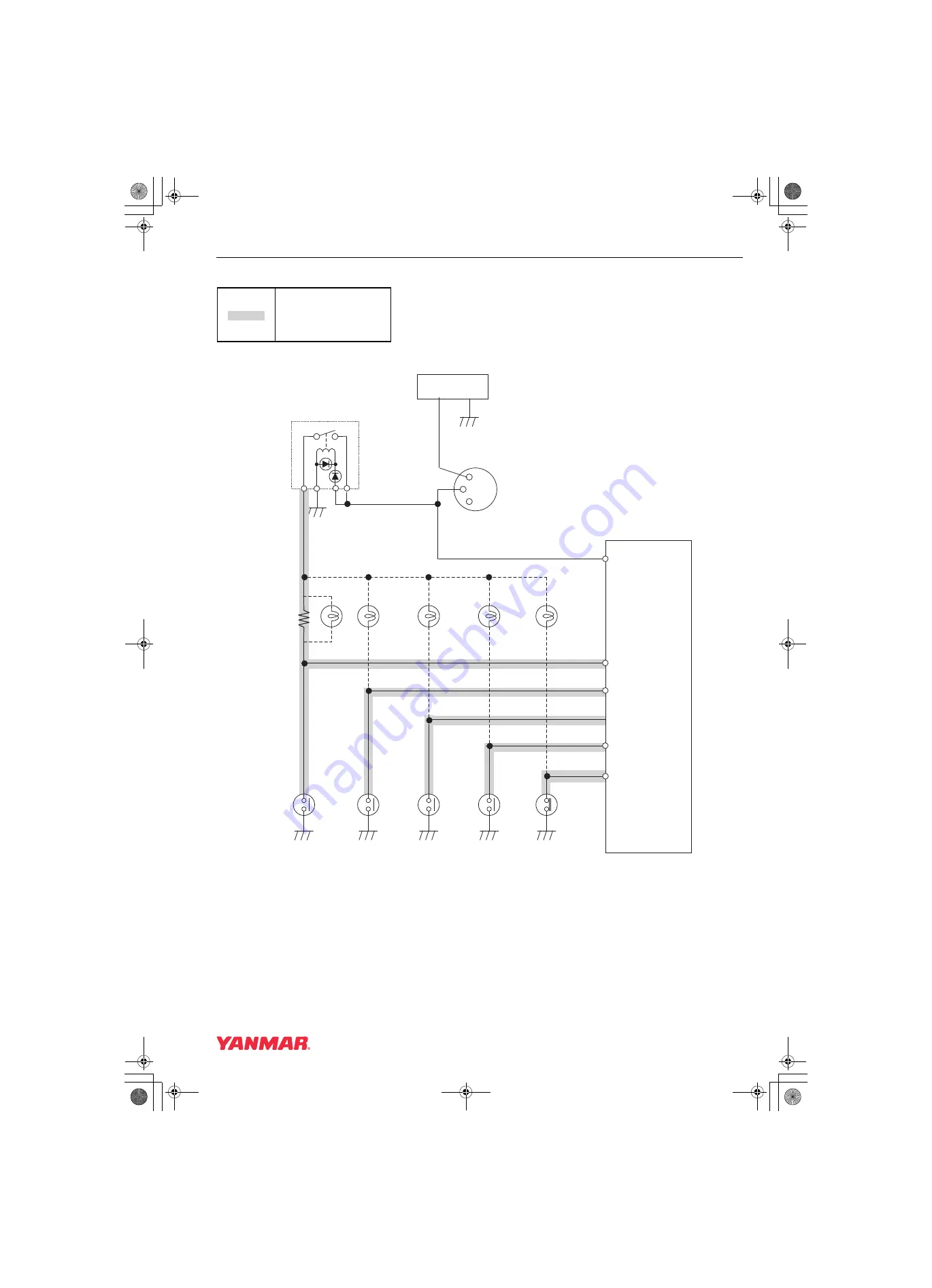
Method and Procedure of Failure Diagnosis
Wiring Diagram
*For the E-ECU Pin Layout, see [E-ECU Pin Layout Diagram] (P.1-134).
: Check points
019613-00E
APP-IP3
E09
E-ECU
APP-IP2
E14
+
−
Battery
E05
E07
APP-IP5
Sub-relay
IGNSW
APP-IP6
E06
Key switch
Oil pressure
switch
Charge
switch
Air
cleaner
Oil-Water
Separator
120Ω
Or
lamp
lamp
lamp
lamp
Water
Temperature
Switch
E17
APP-IP4
lamp
TNV_DI_SM_A4-Troubleshooting.book 189 ページ 2007年11月15日 木曜日 午後5時27分


