FAILURE DIAGNOSIS
TNV DI Service Manual
1-135
Method and Procedure of Failure Diagnosis
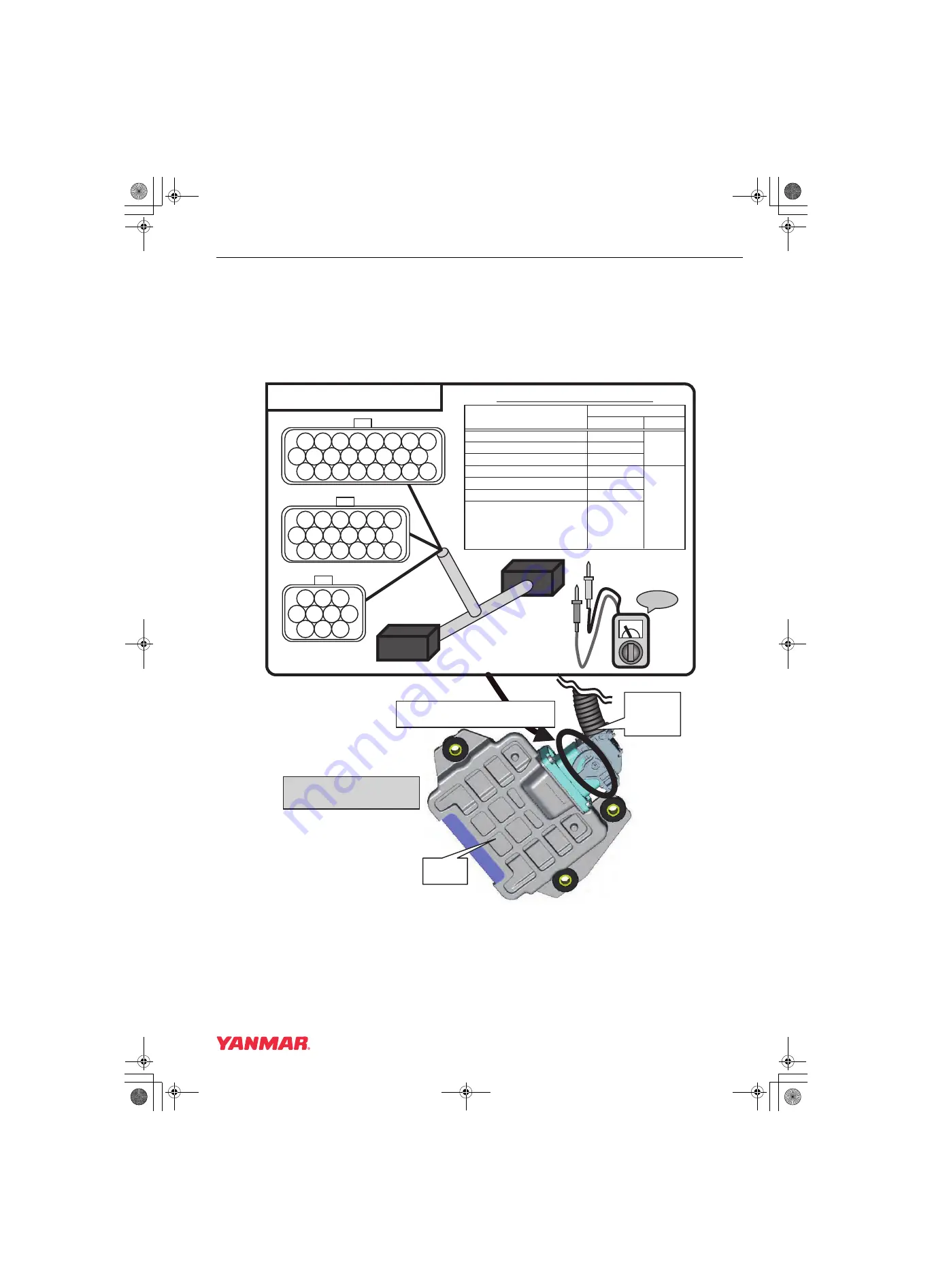
How to use the 2G eco-checker harness
Failure diagnosis for area listed in the following correspondence list includes the work measuring voltage
with the 2G eco-checker harness.Therefore before the failure diagnosis, remove the E-ECU and machine’s
harness, and connect the 2G eco-checker harness between the E-ECU and machine’s harness.
* For details of the failure diagnosis for each area, see the followings.
* Measure the voltage using a circuit tester referring the following list.
E20
E18 E19
E09 E10 E11 E12 E13 E14 E15 E16
E08
E05 E06
E02 E03
E01
E04
E07
E17
E21 E22 E23 E24
E28
E30
E25 E26 E27
E29
E31 E32 E33 E34 E35 E36
E37 E38 E39 E40
--
--
E41 E42 E43
E44 E45 E46 E47
E48
--
--
2G Eco-checker Harness
V
Check !
E-ECU
Machine’s
harness
Connect between E-ECU and
machine’s harness.
(+)
(-)
Pin layout correspondence list
(+)
(-)
Accelerator sensor
E35
Cooling water temperature sensor
E16 (E25)
Sensor 5V
E38
Rack Actuator Relay
E33
Start Assist Relay
E44
CSD Solenoid Valve Coil
E41
EGR valve
(step motor)
E31 (A-Phase)
E21 (B-Phase)
E11 (C-Phase)
E01 (D-Phase)
Circuit tester
Area
E28
E45
019618-00E
Measure the voltage between
specified terminals using a
circuit tester.
TNV_DI_SM_A4-Troubleshooting.book 135 ページ 2007年11月15日 木曜日 午後5時27分


