


SERIES
211
Input shaft
Output
shaft
g. Apply sealer to the stop bolt threads, but not to the
threads at the end of the bolt (approximately 0.20
in.). Install the stop bolt into the shifter.
BEARING ADJUSTMENT
Perform the following procedure if the following com-
ponents have been replaced: input shaft, input shaft bear-
ings, output shaft, thrust washers and output shaft
bearings. This procedure determines the thickness of
shims that must be installed so the tapered roller bearings
properly contact the bearing outer races.
and
1. Install the input shaft, intermediate shaft and output
shafts as described in the Reassembly section.
2. Position the transmission case so the open end is up
and no pressure is being applied to the splined end of the
output shaft.
3. Install the outer bearing races on the input and output
shaft tapered bearings.
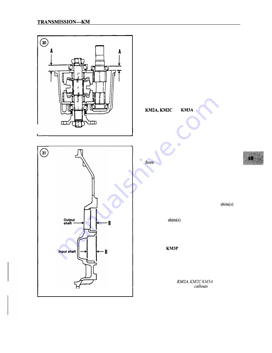
4. Measure the distance (A,
Figure 30) in millimeters
the mounting flange mating surface on the case to
the top of each bearing race. Record the measurements.
5. Measure the distance (B, Figure 31) from the mount-
ing flange mating surface to the bottom of the bearing race
bore for both the input and output shaft bearings.
6. Subtract the A measurement from the B measurement
for each shaft.
7. From the result obtained in Step 6, subtract 0.0-0.05
mm. This result equals the thickness of the
that
must be installed in the bearing bores in the mounting
flange.
8.
Install the
in the bearing bores in the mounting
flange, then press the bearing outer races into the mount-
ing flange on top of the shims. Make sure the races are
bottomed.
KMZP
and
Input shaft
NOTE
The following procedure for adjusting the
input shaft bearings is similar to the proce-
dure for the
transmis-
sions, but only use the
in
Figure 30
and
Figure 31 that pertain to the input
shaft.
Summary of Contents for 1GM10
Page 1: ...YANMAR DIESEL INBOARD SHOP MANUAL ONE TWO 8 THREE CYLINDER ENGINES...
Page 6: ......
Page 7: ......
Page 9: ......
Page 10: ......
Page 11: ......
Page 12: ......
Page 13: ......
Page 16: ......
Page 17: ......
Page 18: ......
Page 19: ......
Page 20: ......
Page 21: ......
Page 22: ......
Page 23: ......
Page 24: ......
Page 25: ......
Page 26: ......
Page 27: ......
Page 28: ...GENERAL INFORMATION 21 Bearing Blocks Press Shaft arm Bearing Spacer Press k 4 bed...
Page 36: ...30 CHAPTER TWO CHARGING SYSTEM TYPICAL Battery switch...
Page 39: ......
Page 44: ...38 CHAPTER TWO LUBRICATION SYSTEM 2GM AND 2GM20 MODELS...
Page 46: ......
Page 50: ......
Page 52: ......
Page 54: ......
Page 55: ......
Page 57: ......
Page 58: ......
Page 64: ......
Page 66: ......
Page 70: ......
Page 71: ......
Page 77: ......
Page 78: ......
Page 79: ......
Page 80: ......
Page 81: ......
Page 82: ......
Page 89: ......
Page 90: ......
Page 91: ......
Page 92: ......
Page 93: ......
Page 94: ......
Page 95: ......
Page 96: ......
Page 97: ......
Page 98: ......
Page 99: ......
Page 100: ......
Page 101: ......
Page 102: ......
Page 112: ...106 CHAPTER SIX...
Page 114: ......
Page 123: ......
Page 124: ......
Page 125: ......
Page 126: ......
Page 129: ......
Page 130: ......
Page 131: ......
Page 133: ......
Page 134: ......
Page 135: ......
Page 136: ......
Page 145: ...FUEL INJECTION AND GOVERNOR SYSTEMS 139 FUEL INJECTION SYSTEM Fuel tank hose fuel pipe...
Page 148: ......
Page 149: ......
Page 150: ......
Page 151: ......
Page 152: ......
Page 153: ......
Page 154: ......
Page 155: ......
Page 156: ......
Page 157: ......
Page 158: ......
Page 165: ......
Page 170: ...164 CHAPTER EIGHT CLOSED COOLING SYSTEM TYPICAL rnlxlng elbow Joint...
Page 172: ......
Page 174: ......
Page 175: ......
Page 176: ......
Page 177: ......
Page 184: ......
Page 190: ......
Page 196: ......
Page 197: ......
Page 201: ......
Page 202: ......
Page 204: ......
Page 205: ......
Page 208: ......
Page 209: ......
Page 219: ......
Page 224: ...218 CHAPTER ELEVEN...
Page 231: ......
Page 235: ......


