70
CHAPTER FIVE
Open
chamber
Fuel injector
chamber
cylinder must not permit compression leakage, which
could lower the temperature of the compressed air. Also,
the cylinder must not contain fuel that could ignite prema-
turely during compression.
Near the end of the compression stroke, fuel is injected
into the cylinder and ignited by compressed air. Fuel in-
jection continues during several degrees of crankshaft ro-
tation, depending upon desired speed and load. Expansion
of the air caused by the burning fuel pushes the piston
down on the expansion (power) stroke.
The exhaust valve opens just before the piston reaches
the bottom of travel. The exhaust valve remains open as
the piston moves upward pushing burned (exhausted) gas-
ses from the cylinder.
Different combustion chamber designs may be used on
diesel engines to accomodate specific engine operating
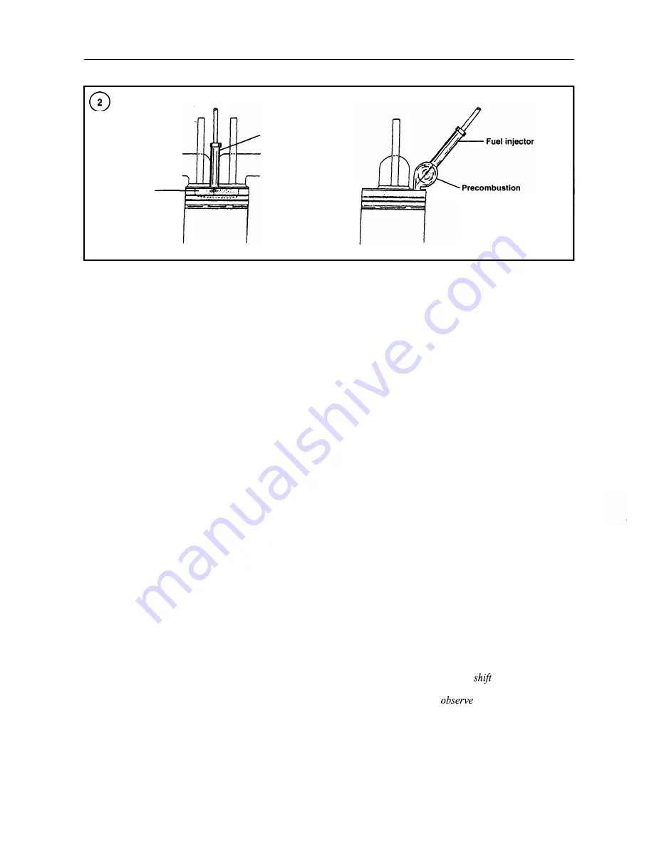
criteria. An open combustion chamber (direct injection)
design is illustrated in Figure 2. The fuel and air are con-
fined to one area. Usually the piston crown is concave to
form the combustion chamber and provide turbulence re-
quired for mixing the fuel with the compressed air. The
shape of the combustion chamber and the shape of the in-
jection spray pattern are matched so that fuel will be dis-
tributed evenly throughout the chamber.
The Yanmar engines covered in this manual are
equipped with a precombustion chamber for each cylinder
(Figure 2). The precombustion chamber increases com-
bustion efficiency, which produces greater power with re-
duced emmissions. Combustion first occurs in the
precombustion chamber when hot, compressed air enters
the precombustion chamber just as fuel is injected. Com-
bustion continues as the fuel and air are mixed and forced
from the precombustion chamber into the engine cylinder.
Additional mixing and ignition are completed in the cylin-
der.
ENGINE SERIAL NUMBER AND CODE
The engine serial number and model designation are lo-
cated on a plate attached to the rocker cover (Figure 3).
The engine serial number is also stamped on the side of
the cylinder block (Figure
4).
Have the engine model number and serial number avail-
able when ordering parts. Record the engine model and
serial numbers and store them for future reference in case
the identification plate on the engine is defaced or lost.
REPLACEMENT PARTS
When installing new parts on the engine, make sure the
part is designed for use on a marine engine. Automotive
and marine engine parts may look similar; however, auto-
motive parts may not be capable of operating in a harsh
marine environment.
Use only Yanmar parts or parts approved for use on ma-
rine engines.
ENGINE REMOVAL PRECAUTIONS
Some service procedures can be performed with the en-
gine in the boat; others require removal. The boat design
and service procedure to be performed determines
whether the engine must be removed.
WARNING
The engine is heavy, awkward to handle and
has sharp edges. It may
or drop sud-
denly during removal. Toprevent serious in-
jury,
always
the following
precautions.
Summary of Contents for 1GM10
Page 1: ...YANMAR DIESEL INBOARD SHOP MANUAL ONE TWO 8 THREE CYLINDER ENGINES...
Page 6: ......
Page 7: ......
Page 9: ......
Page 10: ......
Page 11: ......
Page 12: ......
Page 13: ......
Page 16: ......
Page 17: ......
Page 18: ......
Page 19: ......
Page 20: ......
Page 21: ......
Page 22: ......
Page 23: ......
Page 24: ......
Page 25: ......
Page 26: ......
Page 27: ......
Page 28: ...GENERAL INFORMATION 21 Bearing Blocks Press Shaft arm Bearing Spacer Press k 4 bed...
Page 36: ...30 CHAPTER TWO CHARGING SYSTEM TYPICAL Battery switch...
Page 39: ......
Page 44: ...38 CHAPTER TWO LUBRICATION SYSTEM 2GM AND 2GM20 MODELS...
Page 46: ......
Page 50: ......
Page 52: ......
Page 54: ......
Page 55: ......
Page 57: ......
Page 58: ......
Page 64: ......
Page 66: ......
Page 70: ......
Page 71: ......
Page 77: ......
Page 78: ......
Page 79: ......
Page 80: ......
Page 81: ......
Page 82: ......
Page 89: ......
Page 90: ......
Page 91: ......
Page 92: ......
Page 93: ......
Page 94: ......
Page 95: ......
Page 96: ......
Page 97: ......
Page 98: ......
Page 99: ......
Page 100: ......
Page 101: ......
Page 102: ......
Page 112: ...106 CHAPTER SIX...
Page 114: ......
Page 123: ......
Page 124: ......
Page 125: ......
Page 126: ......
Page 129: ......
Page 130: ......
Page 131: ......
Page 133: ......
Page 134: ......
Page 135: ......
Page 136: ......
Page 145: ...FUEL INJECTION AND GOVERNOR SYSTEMS 139 FUEL INJECTION SYSTEM Fuel tank hose fuel pipe...
Page 148: ......
Page 149: ......
Page 150: ......
Page 151: ......
Page 152: ......
Page 153: ......
Page 154: ......
Page 155: ......
Page 156: ......
Page 157: ......
Page 158: ......
Page 165: ......
Page 170: ...164 CHAPTER EIGHT CLOSED COOLING SYSTEM TYPICAL rnlxlng elbow Joint...
Page 172: ......
Page 174: ......
Page 175: ......
Page 176: ......
Page 177: ......
Page 184: ......
Page 190: ......
Page 196: ......
Page 197: ......
Page 201: ......
Page 202: ......
Page 204: ......
Page 205: ......
Page 208: ......
Page 209: ......
Page 219: ......
Page 224: ...218 CHAPTER ELEVEN...
Page 231: ......
Page 235: ......


