Yamato DL410 Instruction Manual Download Page 29

27 

8. When a trouble occurs 

Safety unit and error indications 

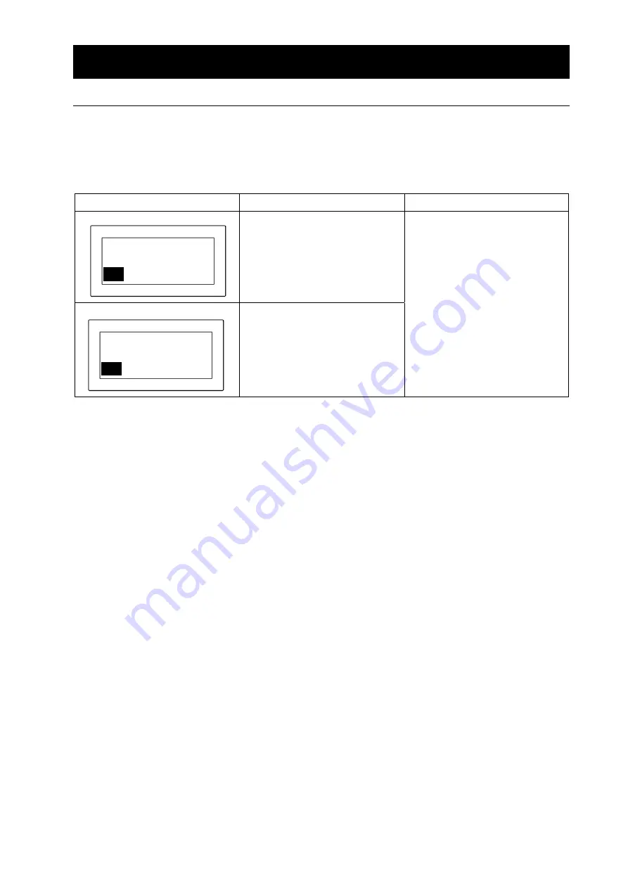
The table shows possible causes of activation of the safety unit and solutions. 

 
[Error indication] 

When an abnormality occurs to the inlet temperature controller or the outlet temperature controller, 

the touch panel at the operation panel displays the error screen. When an abnormality occurred, 
confirm description of the error and implement appropriate solutions. 


Display Possible 

causes Solutions 


 Disconnection of the 

thermocouple sensor 

 When the displayed inlet 

temperature is at 320

°

C or 

over 

 Malfunction of the blower 


 Disconnection of the 

thermocouple sensor 

 When the displayed outlet 

temperature is at 110

°

C or 

over 

 Malfunction of the blower 

 Replacement of the 

thermocouple sensor 


 Lower the set temperature 

or adjust air amount. 


 Replacement of the blower 

*  When the measured temperature exceeds the set upper limit (upper limit of inlet temperature: 

320

°

C; upper limit of outlet temperature: 110

°

C), "Over Heat" will appear, the heater output will stop 

and when that status continues for one minute, the temperature error above will be displayed. The 
safety unit will perform automatic REV operation for five seconds when a temperature error 
occurred while the blower is ON, the heater is OFF, or the liquid sending pump was in operation 
and then shift to the stop mode. 
The same process as shown above will take place when the disconnection of the temperature 
sensor occurred. The temperature controller will indicate "-----". 
Pressing "ESC" key will release the error screen and the status will return to the "BLOWER ON" 
and "HEATER OFF" status. 


Spray Inlet 

Temperature Overheat 


ESC  


ESC  

outlet 

Temperature Overheat 


Summary of Contents for DL410

Page 1: ... this unit properly read this Instruction Manual thoroughly before using this unit Keep this instruction manual around this unit for referring at anytime WARNING Carefully read and thoroughly understand the important warning items described in this manual before using this unit Yamato Scientific America Inc ...

Page 2: ...ator light instruction 19 5 Handling Precautions 20 Maintenance method 21 Drying method under proper condition 22 Matters to consider during operation 23 6 Maintenance Method 24 Daily Inspection and Maintenance 24 7 Long storage and disposal 26 When the unit is not used for long term When disposing 26 Matters to consider when disposing of the unit 26 8 When a trouble occurs 27 Safety unit and erro...

Page 3: ...s or require hospitalization or outpatient visits for a long time Note 2 Minor injury means a wound or an electrical shock that does not require hospitalization or outpatient visits for a long time Note 3 Property damage means damage to facilities devices and buildings or other properties Meanings of symbols This symbol indicates a matter that encourages the user to adhere to warning caution inclu...

Page 4: ... Hazard of explosion Caution General cautions Electrical shock Burning Caution for no liquid heating Caution for water leak For water only Poisonous material Prohibitions General bans Fire ban Do not disassemble Do not touch Compulsions General compulsions Connect ground wire Install levelly Pull out the power plug Regular inspection ...

Page 5: ... is dangerous for non specified service person never repair the unit by the customer himself Do not use the power cord if it is bundled or tangled Do not use the power cord if it is bundled or tangled If it is used in this manner it can overheat and fire could occur Do not damage power cord Do not damage power cord by bending pulling or twisting forcedly It may cause fire or electric shock Besides...

Page 6: ...ecovery from a power failure Do not perform unattended operation during activating the unit Do not perform unattended operation during activating the unit Since the unit is in idling status and the nozzle is blocked of after the operation using sample the temperature around outlet is increased and the remaining sample is flown from the sample tube disconnected from the unit and this failure may ca...

Page 7: ...he color of each core wire when connecting the power cord Core Wire Color In house Wiring Black Voltage Side White Voltage Side Be sure to check that the breaker on the power source equipment side is turned OFF when connecting power cord without fail Note that the DL410 does not attach the power plug as standard component Select the appropriate power plug and terminal matching to the power capacit...

Page 8: ...in DRYING AIR BLOWER PUMP KEY PANEL OUTLET TEMP INLET TEMP 5 Do not use explosive or flammable substances Never use explosive substances flammable substances and substances that include explosive or flammable ingredients in this unit Explosion or fire may occur DL410 supports organic solvents by connecting it to the optional GAS410 Carefully read the operation manual of GAS410 and take special car...

Page 9: ...other device s uses the same power line of this unit If the phenomena might be found change the power line of this unit to the other power line For connecting of the device to the power source ask the dealer that you purchased this unit from or an electrical contractor for safe 9 Handling of power code Do not entangle the power cord This will cause overheating and possibly a fire Do not bend or tw...

Page 10: ...put of 4 20mA Measured temperature of 40 320 C Conversion formula Current output I mA 0 05x measured temperature T C 4 Measured temperature T C 20 current output I mA 80 When you connecting to the voltage input of the recorder connect a fixed resistor shunt resistor of 600Ω or lower to the voltage input of the recorder inlet temp 20 40 4 20mA 320 320 40 mA 4 outlet temp 20mA 4mA 0 320 Measured tem...

Page 11: ...IR 3 m min DRYING AIR BLOWER PUMP KEY PANEL OUTLET TEMP INLET TEMP Nozzle Sample carrier Solvent delivery pump Drying Chamber Upper frame Head Connecting hose Inner Dia φ50 Control box Operation Panel Blower inside sheet metal Cyclone Product catcher Lower chamber Air intake hose Inner Diameter φ38 1 ...

Page 12: ... delivery pump Operation Key Panel Touch Panel For the following operation and display HEAD UP DOWN Blower ON OFF Heater ON OFF Solvent delivery pump FWD REV NOZZLE BLOW and NEEDLE KNOCKER When abnormality occurs on the inlet and outlet temperature ERROR displays Display Outlet Temperature Display the outlet temperature to prevent over lifting Setting and displaying inlet temperature For setting i...

Page 13: ...nector CN21 12p For the temperature sensor on the HEAD and battery valve to connect each other Heater reply connector CN22 3p For connecting to the Head heater Air supply Inlet AIR IN For supplying air into the unit TUBE B For connecting the air pose with the Head TUBE A For connecting the air pose with the Head Temperature output terminal Current output terminal of inlet outlet temperature 4 20mA...

Page 14: ... upper frame The head will rotate by 90 when it lifted by 5cm at this moment please help it lift by hand 12 Open the package take out the drying chamber which is made of super hard glass with 457I D and 975cm height then place it on the stand The chamber is made of glass and of 40 kg weight you ll need at least 2 persons to carry it 13 Fix the up and bottom firm band on the support and stand 14 In...

Page 15: ...t Temp Sensor in front of the control box 21 Install the sample tube on the liquid delivery pump and then connect it to the nipple of the nozzle 22 To solve the hot wind or particles caused by the blower you can install the attached exhaust duct at the vent of the blower inner dia 50mm length 3m with cuffs on each side so that it can exhaust air through the ventilated containers ...

Page 16: ...he Head by using your hand 123 When the HEAD button is ON the HEAD indicator light flickers The HEAD button light is on After setting the drying chamber help its upper chamber to rotate and then return to the upper position of the drying chamber Press down the HEAD button for the drying chamber and the upper part of the chamber to be closely connected The Head indicator light goes out The HEAD but...

Page 17: ...he NEEDLE KNOCKER After the Time Setting button is press the Please input figures within the set range 1 60min then press ENT to confirm If the ESC key is pressed it will automatically jumps from the setup page After the automatic operation period of NEEDLE KNOCKER has been set up Press NEXT to jump to next setup page Press BACK to return to the standby page ...

Page 18: ... 7 Press down HEATER button turn on the heater During operation the Heater indicator light is always on Adjust the INLET TEMP through the button E g INELT TEMP 200 C When pressing the NEEDLE KNOCKER button the needle in front of the spray nozzle will appear on the mesh automatically If the front side of the spray nozzle is clogged it will affect the spraying So please use this function Press on th...

Page 19: ... the attachments with compressed air 10 Readjust the drying air volume spraying pressure and solvent delivery speed to set the inlet and outlet temperature to be stabled at the expected temperature E g Adjust the infuse speed so that the outlet temperature is lowthan85 When the inlet temperature is the same all setting has the following influence on the outlet temperature Sample infuse volume smal...

Page 20: ...nlet temperature is below 45 C switch of the wind volume Turn OFF the Blower To avoid any trouble please do not stop the blower when the outlet temperature is above 45 C 14 Please turn off the power switch 15 Untie the container fasten ribbon take out product catcher At this moment please note there is also powder attached inside the cyclone cover 16 Please follow the cleaning method P24 On cleara...

Page 21: ... indicator light is on it means the heater is working When this indicator light is on it means the solvent delivery pump is working in the forward direction When this indicator light is on it means the solvent delivery pump is working in the reversed direction When the nozzle is clogged and when you want to stop the sampling process In the case the nozzle is clogged when you want to stop the sampl...

Page 22: ...ork yourself since it is dangerous and not recommended 3 Do not touch the part with high temperature The chamber cyclone and peripheral part become high temperature during and just after operation Do not touch these parts for there may be caused heat injury Caution 1 Do not put anything on this unit Do not put anything on this unit It will cause injury if fall 2 During a thunder storm During a thu...

Page 23: ...4 Press down the lower chamber as it moves horizontally take out the chamber from the stand then clean with tap water 5 There are some powder attached on some part as the hot wind from the upper frame please wipe it properly 6 Lower the upper chamber by hand after the upper chamber has return to the upper position of the drying chamber turn the HEAD switch to DOWN so that the drying chamber and th...

Page 24: ...oo high or too low etc After drying 70 85 of samples will be recycled to the product catcher the remaining 15 30 samples will be attached to the drying chamber If there are serious problems on the chamber please adjust following the above instructions 4 If the hygroscopicity of the sample is high it will leave wet powder inside the product catcher In this case you can follow the instruction in 2 t...

Page 25: ...ng operation if you want to disassemble the nozzle tube B please stop the automatic operation of NEEDLE KNOCKER first To remove the nozzle tube A please switch off the needle valve first 7 The nozzle mesh is around 0 7mm When the sample is severely clogged please use our parts to remove the clog this part has a bigger diameter than the mesh 8 If the sample does not deliver from the liquid delivery...

Page 26: ...ay result in ベンジン シンナー クレンザー Cleaning After Using 1 After completing the operation remove the attachments following the process Preparations on P 11 in reverse order 2 Clean the portion of attachment to which the powder is adhered 3 Flow the distilled water into the sample tube by pressing the pump switch and remove the contaminant attached to the inner of the part 4 Remove the spray air tube and ...

Page 27: ...ng the filter after being immersed into the solvent that hot water approx 40 Celsius degree and neutral detergent are mixed at a rate of 5 95 one whole day and night then rinse it with water and air dry it 4 When assembling reversely execute the above procedure Turn the soft surface of the filter to windward when installing the filter Suction filter Regularly clean the suction filter 1 The suction...

Page 28: ...ed We request you to disassemble this unit as possible and recycle the reusable parts considering to the environmental protection The feature components of this unit and materials used are listed below Component Name Material Parts of Main Unit Casing Bonderizing steel plate baked with melamine resin coating Stainless steel Insulating material Ceramic Felton Specimen bed Stainless steel Production...

Page 29: ... thermocouple sensor Lower the set temperature or adjust air amount Replacement of the blower When the measured temperature exceeds the set upper limit upper limit of inlet temperature 320 C upper limit of outlet temperature 110 C Over Heat will appear the heater output will stop and when that status continues for one minute the temperature error above will be displayed The safety unit will perfor...

Page 30: ...or z Activated the protection circuit without turning on the blower switch z Heater disconnection z Heater switch failure z Heater circuit failure and wiring failure z Connect correctly z Solve the problem and turn ON the switch z Turn ON the blower and then turn ON the heater switch z Replace the part z Replace the touch panel or sequencer z Maintain the part or replace the thermo regulator Feedi...

Page 31: ...flow z Maintain the part or replace the thermo regulator z No error For operating this unit with high temperature decrease the flow rate of the drying air or increase the setting value HEAD lifting failure z Compressed air supply deficiency z Air tank failure z Magnetic valve failure for Head lifting z Set the pressure of the pressure reducing valve to 0 4 Mpa lift the Head part by hand z Replace ...

Page 32: ...and other information and send it to our customer service center by Facsimile 03 3231 6523 Then store it securely Warranty period is one full year from the date of purchase Repair service for free is available according to the conditions written on the warranty card For repairs after the warranty period consult your dealer one of our sales offices or our customer service center Paid repair service...

Page 33: ...tomatically Drive the air tank inside the nozzle through magnetic valve electric timer and compressed air Nozzle Blower Blow away the powder attached on the nozzle head Use magnetic valve Compressed air Head lifting mechanism Automatic UP DOWN of Head where the hot wind blown out Drive the air tank inside the upper frame by using magnetic valve and compressed air Power supply AC220V single phase 5...

Page 34: ...Y0 BY0 Br ow n Col or Red O r ange Yel l ow RDB RDA SDB GO T t er m i nal SDA T Panel 0V 0FF CCW ON CW Gr een SG Bl ack W hi t e CSB CSA RSB RSA GT1030 LBDW FX1N 24M R COM 5 Y0 Y20 Y1 Y21 Y2 Y22 Y3 Y23 Y4 Y24 Y1 Y31 Y0 Y30 CO M 6 Y7 Y27 Y6 Y26 Y5 Y25 F X 0 N 16 E Y R DC 24V PO W ER CN2 CN1 4 3 1 2 5 1 3 0V DC24V 0V DC24V 2 1 3 Back vi ew 3 2 1 M 1 VR1 CN2 G V Vi n CN3 FSC PC T N P 黄 红 青 E CN1 S R ...

Page 35: ...ecting hose Drying chamber Spray air pressure gauge Upper chamber Lower chamber NEEDLE KNOCKER for magnetic valve Conversion solenoid valve Cyclone nozzle Blower use magnetic valve Conversion solenoid valve product catcher Cold wind adjusting valve Manual valve Blower use magnetic valve for Head lifting and descending GAS N2 GAS IN GAS410 PRESSURE AIR IN ...

Page 36: ...go through the wall of upper chamber by cold wind valve manual valve This can prevent the powder from attaching to the upper chamber The temperature condition for testing displays on the temperature adjuster through the inlet temperature sensor and outlet temperature sensor The temperature can be recorded by installing a temperature recorder on the temperature output terminal In addition the air f...

Page 37: ...070001 Needle valve 2412T B 7 Φ4 30 50L min YSC R0070040 Dry air flow meter O 186 FB YSC LT00034057 Gears LRA25 20S B10K YSC A101A045S0 Brushless motor BBW1006BL2E Blower YSC LT00029635 FSC PC Drive SPA1006BL4 Blower YSC LT00029636 M2 Motor FY8PF15ND3 for solvent delivery YSC LT00027675 PUMP PC Drive circuit board FYD815SD3 for solvent delivery YSC LT00027693 Gear head 8H30FBN100 for solvent deliv...

Page 38: ...Spring B for Cyclone DL 41 212708 149 YSC B050232009 Tube connector straight GWS6 8 YSJ SJA06842 Tube connector straight GWS6 6 YSJ SJA06841 Tube connector joint of bended tube GWL6 8 YSJ SJA06840 Tube connector joint of long bended tube GWL6 8 L YSJ SJA06839 D type Tube connector Shunt circuit T GWT6 6 D YSJ SJA07544 D type tube connector Shunt circuit T GWT6 8 D YSJ SJA06838 Bulkhead push in fit...

Page 39: ...er chlorates Potassium perchlorate sodium perchlorate ammonium perchlorate and other perchlorates Potassium peroxide sodium peroxide barium peroxide and other inorganic peroxides Potassium nitrate sodium nitrate ammonium nitrate and other nitrates Sodium chlorite and other chlorites Oxidizing substances Calcium hypochlorite and other hypochlorites Ethyl ether gasoline acetaldehyde propylene chlori...

Page 40: ...bids Unexpected accidents or breakdown may result in Note The contents of this document may be changed in future without notice Any books with missing pages or disorderly binding may be replaced Instruction Manual Spray Dryer DL410 Version Feb 25 2009 Revision September 28 2012 Yamato Scientific America Inc 925 Walsh Ave Santa Clara CA 95050 Tel 408 235 7725 For technical information and service c...

Reviews: