ELECTRICAL COMPONENTS
8-126
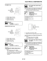
c. Turn the main switch to “ON”.
d. Measure the intake air pressure sensor
output voltage.
▲▲▲▲▲▲▲▲▲▲▲▲▲▲▲▲▲▲▲▲▲▲▲▲▲▲▲▲▲▲
EAS28420
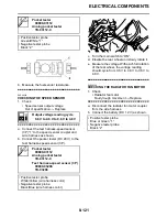
CHECKING THE INTAKE AIR TEMPERA-
TURE SENSOR
1. Remove:
• Intake air temperature sensor
(from the headlight assembly.)
WARNING
EWA14110
• Handle the intake air temperature sensor
with special care.
• Never subject the intake air temperature
sensor to strong shocks. If the intake air
temperature sensor is dropped, replace it.
2. Check:
• Intake air temperature sensor resistance
Out of specification
→
Replace.
▼▼▼▼▼▼▼▼▼▼▼▼▼▼▼▼▼▼▼▼▼▼▼▼▼▼▼▼▼▼
a. Connect the pocket tester (
Ω
×
100) to the
intake air temperature sensor terminal as
shown.
b. Immerse the intake air temperature sensor
“1” in a container filled with water “2”.
TIP
Make sure that the intake air temperature sen-
sor terminals do not get wet.
c. Place a thermometer “3” in the water.
d. Slowly heat the water, then let it cool down
to the specified temperature.
e. Measure the intake air temperature sensor
resistance.
▲▲▲▲▲▲▲▲▲▲▲▲▲▲▲▲▲▲▲▲▲▲▲▲▲▲▲▲▲▲
3. Install:
• Intake air temperature sensor
EAS14B1020
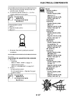
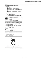
CHECKING THE STEERING DAMPER
SOLENOID
1. Remove:
• Left side cowling
Refer to “GENERAL CHASSIS” on page
4-1.
2. Check:
• Steering damper solenoid resistance
Out of specification
→
Replace the steer-
ing damper assembly.
Digital circuit tester
90890-03174
Model 88 Multimeter with
tachometer
YU-A1927
Test harness S-pressure sensor
5S7 (3P)
90890-03211
YU-03211
• Positive tester probe
Pink/White (wire harness color)
• Negative tester probe
Black/Blue (wire harness color)
Intake air temperature sensor
resistance
5.4–6.6 k
Ω
at 0
°
C (32
°
F)
290–390
Ω
at 80
°
C (176
°
F)
Pocket tester
90890-03112
Analog pocket tester
YU-03112-C
Intake air temperature sensor
screw
1.5 Nm (0.15 m·kgf, 1.1 ft·lbf)
Steering damper solenoid resis-
tance
49.82–56.18
Ω
at 20
°
C (68
°
F)
Summary of Contents for YZFR1Y(C) 2009
Page 1: ...SERVICE MANUAL YZFR1Y C 14B 28197 10 LIT 11616 22 78 2009 ...
Page 6: ......
Page 8: ......
Page 36: ...SPECIAL TOOLS 1 27 ...
Page 66: ...LUBRICATION SYSTEM CHART AND DIAGRAMS 2 29 EAS20410 LUBRICATION DIAGRAMS ...
Page 68: ...LUBRICATION SYSTEM CHART AND DIAGRAMS 2 31 ...
Page 70: ...LUBRICATION SYSTEM CHART AND DIAGRAMS 2 33 ...
Page 72: ...LUBRICATION SYSTEM CHART AND DIAGRAMS 2 35 ...
Page 73: ...LUBRICATION SYSTEM CHART AND DIAGRAMS 2 36 1 Main axle 2 Oil water pump assembly ...
Page 74: ...LUBRICATION SYSTEM CHART AND DIAGRAMS 2 37 ...
Page 75: ...LUBRICATION SYSTEM CHART AND DIAGRAMS 2 38 1 Main axle 2 Oil delivery pipe 2 3 Drive axle ...
Page 76: ...LUBRICATION SYSTEM CHART AND DIAGRAMS 2 39 ...
Page 78: ...LUBRICATION SYSTEM CHART AND DIAGRAMS 2 41 ...
Page 80: ...LUBRICATION SYSTEM CHART AND DIAGRAMS 2 43 ...
Page 81: ...LUBRICATION SYSTEM CHART AND DIAGRAMS 2 44 1 Balancer shaft 2 Crankshaft ...
Page 82: ...COOLING SYSTEM DIAGRAMS 2 45 EAS20420 COOLING SYSTEM DIAGRAMS ...
Page 84: ...COOLING SYSTEM DIAGRAMS 2 47 ...
Page 85: ...COOLING SYSTEM DIAGRAMS 2 48 1 Radiator cap 2 Radiator 3 Radiator fan 4 Oil cooler ...
Page 86: ...CABLE ROUTING 2 49 EAS20430 CABLE ROUTING ...
Page 88: ...CABLE ROUTING 2 51 ...
Page 90: ...CABLE ROUTING 2 53 ...
Page 92: ...CABLE ROUTING 2 55 ...
Page 94: ...CABLE ROUTING 2 57 ...
Page 96: ...CABLE ROUTING 2 59 ...
Page 98: ...CABLE ROUTING 2 61 ...
Page 100: ...CABLE ROUTING 2 63 ...
Page 102: ...CABLE ROUTING 2 65 ...
Page 104: ...CABLE ROUTING 2 67 ...
Page 106: ...CABLE ROUTING 2 69 ...
Page 108: ...CABLE ROUTING 2 71 ...
Page 110: ...CABLE ROUTING 2 73 ...
Page 113: ......
Page 148: ...PERIODIC MAINTENANCE 3 35 ...
Page 253: ...ENGINE REMOVAL 5 12 Installed depth of gasket c 3 5 mm 0 14 in ...
Page 286: ...PICKUP ROTOR 5 45 Yamaha bond No 1215 Three Bond No 1215 90890 85505 ...
Page 291: ...ELECTRIC STARTER 5 50 ...
Page 340: ...TRANSMISSION 5 99 ...
Page 356: ...WATER PUMP 6 15 ...
Page 378: ...AIR INDUCTION SYSTEM 7 21 EAS27040 AIR INDUCTION SYSTEM ...
Page 384: ...AIR INDUCTION SYSTEM 7 27 ...
Page 387: ......
Page 388: ...IGNITION SYSTEM 8 1 EAS27090 IGNITION SYSTEM EAS27110 CIRCUIT DIAGRAM ...
Page 394: ...ELECTRIC STARTING SYSTEM 8 7 EAS27160 ELECTRIC STARTING SYSTEM EAS27170 CIRCUIT DIAGRAM ...
Page 400: ...CHARGING SYSTEM 8 13 EAS27200 CHARGING SYSTEM EAS27210 CIRCUIT DIAGRAM ...
Page 403: ...CHARGING SYSTEM 8 16 ...
Page 404: ...LIGHTING SYSTEM 8 17 EAS27240 LIGHTING SYSTEM EAS27250 CIRCUIT DIAGRAM ...
Page 408: ...SIGNALING SYSTEM 8 21 EAS27270 SIGNALING SYSTEM EAS27280 CIRCUIT DIAGRAM ...
Page 415: ...SIGNALING SYSTEM 8 28 ...
Page 416: ...COOLING SYSTEM 8 29 EAS27300 COOLING SYSTEM EAS27310 CIRCUIT DIAGRAM ...
Page 419: ...COOLING SYSTEM 8 32 ...
Page 420: ...FUEL INJECTION SYSTEM 8 33 EAS27330 FUEL INJECTION SYSTEM EAS27340 CIRCUIT DIAGRAM ...
Page 484: ...FUEL PUMP SYSTEM 8 97 EAS27550 FUEL PUMP SYSTEM EAS27560 CIRCUIT DIAGRAM ...
Page 488: ...ELECTRICAL COMPONENTS 8 101 EAS27972 ELECTRICAL COMPONENTS ...
Page 490: ...ELECTRICAL COMPONENTS 8 103 ...
Page 492: ...ELECTRICAL COMPONENTS 8 105 EAS27980 CHECKING THE SWITCHES ...
Page 516: ...ELECTRICAL COMPONENTS 8 129 ...
Page 523: ......
Page 524: ...YAMAHA MOTOR CO LTD 2500 SHINGAI IWATA SHIZUOKA JAPAN ...
Page 525: ...WIRING DIAGRAM YZFR1Y C ...
Page 526: ...WIRING DIAGRAM YZFR1Y C ...


