


CAMSHAFTS
5-22
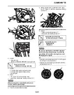
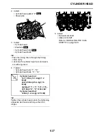
6. Install:
• Exhaust camshaft “1”
• Intake camshafts “2”
TIP
• Hang the timing chain on the sprocket from
the exhaust camshaft to the intake camshaft,
and then put it on the cylinder head.
• The intake camshaft sprocket air intake tim-
ing mark “a” and exhaust camshaft sprocket
air exhaust timing mark “b” should align with
the cylinder head surface “c”.
• The timing chain (exhaust side) should be
stretched and the timing chain (intake side)
should be sagged.
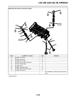
7. Install:
• Dowel pins
• Intake camshaft caps
• Exhaust camshaft caps
TIP
• Make sure each camshaft cap is installed in
its original place. Refer to the identification
marks as follows:
“I”: Intake side camshaft cap mark
“E”: Exhaust side camshaft cap mark
“IL”: Intake left side camshaft cap mark
“IR”: Intake right side camshaft cap mark
“EL”: Exhaust left side camshaft cap mark
“ER”: Exhaust right side camshaft cap mark
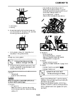
• Make sure the arrow mark “a” on each cam-
shaft points towards the right side of the
engine.
• When installing the camshaft cap, face the
hole with the screw thread “b” on the cam-
shaft cap to the left side of the engine.
8. Install:
• Camshaft cap bolts
ECA14B1011
• Lubricate the camshaft cap bolts with the
engine oil.
• The camshaft cap bolts must be tightened
evenly or damage to the cylinder head,
camshaft caps, and camshafts will result.
• Do not turn the crankshaft when installing
the camshaft to avoid damage or
improper valve timing.
TIP
Tighten the camshaft cap bolts in stages and
in a crisscross pattern, working from the inner
caps out.
9. Install:
• Timing chain tensioner
▼▼▼▼▼▼▼▼▼▼▼▼▼▼▼▼▼▼▼▼▼▼▼▼▼▼▼▼▼▼
a. Using a hand press, push and insert timing
chain tensioner rod “1” into the timing chain
tensioner housing.
TIP
Push the timing chain tensioner rod in direction
“a”, and turn the timing chain tensioner body
“2” in direction “b” until it stops.
A. Right side
B. Left side
Camshaft cap bolt
10 Nm (1.0 m·kgf, 7.2 ft·lbf)
Summary of Contents for YZFR1Y(C) 2009
Page 1: ...SERVICE MANUAL YZFR1Y C 14B 28197 10 LIT 11616 22 78 2009 ...
Page 6: ......
Page 8: ......
Page 36: ...SPECIAL TOOLS 1 27 ...
Page 66: ...LUBRICATION SYSTEM CHART AND DIAGRAMS 2 29 EAS20410 LUBRICATION DIAGRAMS ...
Page 68: ...LUBRICATION SYSTEM CHART AND DIAGRAMS 2 31 ...
Page 70: ...LUBRICATION SYSTEM CHART AND DIAGRAMS 2 33 ...
Page 72: ...LUBRICATION SYSTEM CHART AND DIAGRAMS 2 35 ...
Page 73: ...LUBRICATION SYSTEM CHART AND DIAGRAMS 2 36 1 Main axle 2 Oil water pump assembly ...
Page 74: ...LUBRICATION SYSTEM CHART AND DIAGRAMS 2 37 ...
Page 75: ...LUBRICATION SYSTEM CHART AND DIAGRAMS 2 38 1 Main axle 2 Oil delivery pipe 2 3 Drive axle ...
Page 76: ...LUBRICATION SYSTEM CHART AND DIAGRAMS 2 39 ...
Page 78: ...LUBRICATION SYSTEM CHART AND DIAGRAMS 2 41 ...
Page 80: ...LUBRICATION SYSTEM CHART AND DIAGRAMS 2 43 ...
Page 81: ...LUBRICATION SYSTEM CHART AND DIAGRAMS 2 44 1 Balancer shaft 2 Crankshaft ...
Page 82: ...COOLING SYSTEM DIAGRAMS 2 45 EAS20420 COOLING SYSTEM DIAGRAMS ...
Page 84: ...COOLING SYSTEM DIAGRAMS 2 47 ...
Page 85: ...COOLING SYSTEM DIAGRAMS 2 48 1 Radiator cap 2 Radiator 3 Radiator fan 4 Oil cooler ...
Page 86: ...CABLE ROUTING 2 49 EAS20430 CABLE ROUTING ...
Page 88: ...CABLE ROUTING 2 51 ...
Page 90: ...CABLE ROUTING 2 53 ...
Page 92: ...CABLE ROUTING 2 55 ...
Page 94: ...CABLE ROUTING 2 57 ...
Page 96: ...CABLE ROUTING 2 59 ...
Page 98: ...CABLE ROUTING 2 61 ...
Page 100: ...CABLE ROUTING 2 63 ...
Page 102: ...CABLE ROUTING 2 65 ...
Page 104: ...CABLE ROUTING 2 67 ...
Page 106: ...CABLE ROUTING 2 69 ...
Page 108: ...CABLE ROUTING 2 71 ...
Page 110: ...CABLE ROUTING 2 73 ...
Page 113: ......
Page 148: ...PERIODIC MAINTENANCE 3 35 ...
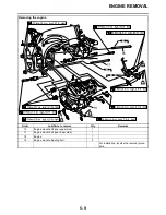
Page 253: ...ENGINE REMOVAL 5 12 Installed depth of gasket c 3 5 mm 0 14 in ...
Page 286: ...PICKUP ROTOR 5 45 Yamaha bond No 1215 Three Bond No 1215 90890 85505 ...
Page 291: ...ELECTRIC STARTER 5 50 ...
Page 340: ...TRANSMISSION 5 99 ...
Page 356: ...WATER PUMP 6 15 ...
Page 378: ...AIR INDUCTION SYSTEM 7 21 EAS27040 AIR INDUCTION SYSTEM ...
Page 384: ...AIR INDUCTION SYSTEM 7 27 ...
Page 387: ......
Page 388: ...IGNITION SYSTEM 8 1 EAS27090 IGNITION SYSTEM EAS27110 CIRCUIT DIAGRAM ...
Page 394: ...ELECTRIC STARTING SYSTEM 8 7 EAS27160 ELECTRIC STARTING SYSTEM EAS27170 CIRCUIT DIAGRAM ...
Page 400: ...CHARGING SYSTEM 8 13 EAS27200 CHARGING SYSTEM EAS27210 CIRCUIT DIAGRAM ...
Page 403: ...CHARGING SYSTEM 8 16 ...
Page 404: ...LIGHTING SYSTEM 8 17 EAS27240 LIGHTING SYSTEM EAS27250 CIRCUIT DIAGRAM ...
Page 408: ...SIGNALING SYSTEM 8 21 EAS27270 SIGNALING SYSTEM EAS27280 CIRCUIT DIAGRAM ...
Page 415: ...SIGNALING SYSTEM 8 28 ...
Page 416: ...COOLING SYSTEM 8 29 EAS27300 COOLING SYSTEM EAS27310 CIRCUIT DIAGRAM ...
Page 419: ...COOLING SYSTEM 8 32 ...
Page 420: ...FUEL INJECTION SYSTEM 8 33 EAS27330 FUEL INJECTION SYSTEM EAS27340 CIRCUIT DIAGRAM ...
Page 484: ...FUEL PUMP SYSTEM 8 97 EAS27550 FUEL PUMP SYSTEM EAS27560 CIRCUIT DIAGRAM ...
Page 488: ...ELECTRICAL COMPONENTS 8 101 EAS27972 ELECTRICAL COMPONENTS ...
Page 490: ...ELECTRICAL COMPONENTS 8 103 ...
Page 492: ...ELECTRICAL COMPONENTS 8 105 EAS27980 CHECKING THE SWITCHES ...
Page 516: ...ELECTRICAL COMPONENTS 8 129 ...
Page 523: ......
Page 524: ...YAMAHA MOTOR CO LTD 2500 SHINGAI IWATA SHIZUOKA JAPAN ...
Page 525: ...WIRING DIAGRAM YZFR1Y C ...
Page 526: ...WIRING DIAGRAM YZFR1Y C ...