FRONT FORK
4-69
TIP
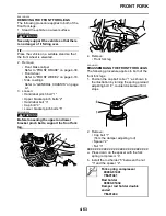
Use the side of the rod holder that is marked
“B”.
j.
Remove the rod puller and rod puller
attachment.
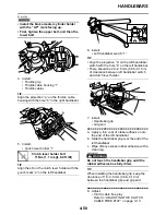
k. Install the nut “1” all the way onto the
damper rod assembly.
l.
Install the damper adjusting valve spring,
the damper adjusting valve and the damper
adjusting rod.
m. Install the washer and cap bolt, and then
finger tighten the cap bolt.
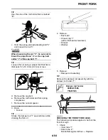
n. Hold the nut and tighten the spring preload
adjusting bolt “2” into the cap bolt to specifi-
cation.
WARNING
EWA14B1011
Always use a new cap bolt O-ring.
ECA14B1009
When tightening the spring preload adjust-
ing bolt “2” into the cap bolt, be sure not to
break the projections “a” on the cap bolt
collar “3”.
TIP
Hold the nut “1” using a proper tool that has a
thickness “b” of 4.0 mm (0.16 in) or less.
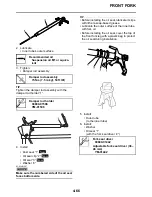
o. Remove the rod holder and fork spring
compressor.
▲▲▲▲▲▲▲▲▲▲▲▲▲▲▲▲▲▲▲▲▲▲▲▲▲▲▲▲▲▲
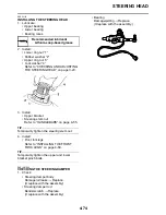
16. Install:
• Cap bolt
(to the outer tube)
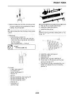
TIP
• Temporarily tighten the cap bolt.
• When to tighten the cap bolt to the specified
torque is after installing the front fork leg to
the vehicle and tightening the lower bracket
pinch bolts.
EAS14B1009
INSTALLING THE FRONT FORK LEGS
The following procedure applies to both of the
front fork legs.
Rod puller
90890-01437
Universal damping rod bleeding
tool set
YM-A8703
Rod puller attachment (M10)
90890-01436
Universal damping rod bleeding
tool set
YM-A8703
Fork spring compressor
90890-01441
YM-01441
Rod holder
90890-01434
Damper rod holder double
ended
YM-01434
Nut and cap bolt
25 Nm (2.5 m·kgf, 18 ft·lbf)
Summary of Contents for YZFR1Y(C) 2009
Page 1: ...SERVICE MANUAL YZFR1Y C 14B 28197 10 LIT 11616 22 78 2009 ...
Page 6: ......
Page 8: ......
Page 36: ...SPECIAL TOOLS 1 27 ...
Page 66: ...LUBRICATION SYSTEM CHART AND DIAGRAMS 2 29 EAS20410 LUBRICATION DIAGRAMS ...
Page 68: ...LUBRICATION SYSTEM CHART AND DIAGRAMS 2 31 ...
Page 70: ...LUBRICATION SYSTEM CHART AND DIAGRAMS 2 33 ...
Page 72: ...LUBRICATION SYSTEM CHART AND DIAGRAMS 2 35 ...
Page 73: ...LUBRICATION SYSTEM CHART AND DIAGRAMS 2 36 1 Main axle 2 Oil water pump assembly ...
Page 74: ...LUBRICATION SYSTEM CHART AND DIAGRAMS 2 37 ...
Page 75: ...LUBRICATION SYSTEM CHART AND DIAGRAMS 2 38 1 Main axle 2 Oil delivery pipe 2 3 Drive axle ...
Page 76: ...LUBRICATION SYSTEM CHART AND DIAGRAMS 2 39 ...
Page 78: ...LUBRICATION SYSTEM CHART AND DIAGRAMS 2 41 ...
Page 80: ...LUBRICATION SYSTEM CHART AND DIAGRAMS 2 43 ...
Page 81: ...LUBRICATION SYSTEM CHART AND DIAGRAMS 2 44 1 Balancer shaft 2 Crankshaft ...
Page 82: ...COOLING SYSTEM DIAGRAMS 2 45 EAS20420 COOLING SYSTEM DIAGRAMS ...
Page 84: ...COOLING SYSTEM DIAGRAMS 2 47 ...
Page 85: ...COOLING SYSTEM DIAGRAMS 2 48 1 Radiator cap 2 Radiator 3 Radiator fan 4 Oil cooler ...
Page 86: ...CABLE ROUTING 2 49 EAS20430 CABLE ROUTING ...
Page 88: ...CABLE ROUTING 2 51 ...
Page 90: ...CABLE ROUTING 2 53 ...
Page 92: ...CABLE ROUTING 2 55 ...
Page 94: ...CABLE ROUTING 2 57 ...
Page 96: ...CABLE ROUTING 2 59 ...
Page 98: ...CABLE ROUTING 2 61 ...
Page 100: ...CABLE ROUTING 2 63 ...
Page 102: ...CABLE ROUTING 2 65 ...
Page 104: ...CABLE ROUTING 2 67 ...
Page 106: ...CABLE ROUTING 2 69 ...
Page 108: ...CABLE ROUTING 2 71 ...
Page 110: ...CABLE ROUTING 2 73 ...
Page 113: ......
Page 148: ...PERIODIC MAINTENANCE 3 35 ...
Page 253: ...ENGINE REMOVAL 5 12 Installed depth of gasket c 3 5 mm 0 14 in ...
Page 286: ...PICKUP ROTOR 5 45 Yamaha bond No 1215 Three Bond No 1215 90890 85505 ...
Page 291: ...ELECTRIC STARTER 5 50 ...
Page 340: ...TRANSMISSION 5 99 ...
Page 356: ...WATER PUMP 6 15 ...
Page 378: ...AIR INDUCTION SYSTEM 7 21 EAS27040 AIR INDUCTION SYSTEM ...
Page 384: ...AIR INDUCTION SYSTEM 7 27 ...
Page 387: ......
Page 388: ...IGNITION SYSTEM 8 1 EAS27090 IGNITION SYSTEM EAS27110 CIRCUIT DIAGRAM ...
Page 394: ...ELECTRIC STARTING SYSTEM 8 7 EAS27160 ELECTRIC STARTING SYSTEM EAS27170 CIRCUIT DIAGRAM ...
Page 400: ...CHARGING SYSTEM 8 13 EAS27200 CHARGING SYSTEM EAS27210 CIRCUIT DIAGRAM ...
Page 403: ...CHARGING SYSTEM 8 16 ...
Page 404: ...LIGHTING SYSTEM 8 17 EAS27240 LIGHTING SYSTEM EAS27250 CIRCUIT DIAGRAM ...
Page 408: ...SIGNALING SYSTEM 8 21 EAS27270 SIGNALING SYSTEM EAS27280 CIRCUIT DIAGRAM ...
Page 415: ...SIGNALING SYSTEM 8 28 ...
Page 416: ...COOLING SYSTEM 8 29 EAS27300 COOLING SYSTEM EAS27310 CIRCUIT DIAGRAM ...
Page 419: ...COOLING SYSTEM 8 32 ...
Page 420: ...FUEL INJECTION SYSTEM 8 33 EAS27330 FUEL INJECTION SYSTEM EAS27340 CIRCUIT DIAGRAM ...
Page 484: ...FUEL PUMP SYSTEM 8 97 EAS27550 FUEL PUMP SYSTEM EAS27560 CIRCUIT DIAGRAM ...
Page 488: ...ELECTRICAL COMPONENTS 8 101 EAS27972 ELECTRICAL COMPONENTS ...
Page 490: ...ELECTRICAL COMPONENTS 8 103 ...
Page 492: ...ELECTRICAL COMPONENTS 8 105 EAS27980 CHECKING THE SWITCHES ...
Page 516: ...ELECTRICAL COMPONENTS 8 129 ...
Page 523: ......
Page 524: ...YAMAHA MOTOR CO LTD 2500 SHINGAI IWATA SHIZUOKA JAPAN ...
Page 525: ...WIRING DIAGRAM YZFR1Y C ...
Page 526: ...WIRING DIAGRAM YZFR1Y C ...

