PERIODIC MAINTENANCE
3-14
WARNING
EWA13090
• Use only the designated brake fluid.
Other brake fluids may cause the rubber
seals to deteriorate, causing leakage and
poor brake performance.
• Refill with the same type of brake fluid
that is already in the system. Mixing brake
fluids may result in a harmful chemical
reaction, leading to poor brake perfor-
mance.
• When refilling, be careful that water does
not enter the brake fluid reservoir. Water
will significantly lower the boiling point of
the brake fluid and could cause vapor
lock.
ECA13540
Brake fluid may damage painted surfaces
and plastic parts. Therefore, always clean
up any spilt brake fluid immediately.
TIP
In order to ensure a correct reading of the
brake fluid level, make sure the top of the
brake fluid reservoir is horizontal.
EAS21160
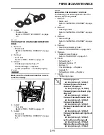
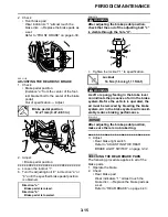
ADJUSTING THE FRONT DISC BRAKE
1. Adjust:
• Brake lever position
(distance “a” from the throttle grip to the
brake lever)
TIP
While pushing the brake lever forward, turn the
adjusting dial “1” until the brake lever is in the
desired position.
WARNING
EWA13060
• After adjusting the brake lever position,
make sure the pin on the brake lever
holder is firmly inserted in the hole in the
adjusting dial.
• A soft or spongy feeling in the brake lever
can indicate the presence of air in the
brake system. Before the vehicle is oper-
ated, the air must be removed by bleeding
the brake system. Air in the brake system
will considerably reduce in loss of control
and possibly an accident. Therefore,
check and if necessary, bleed the brake
system.
ECA13490
After adjusting the brake lever position,
make sure there is no brake drag.
EAS21250
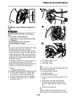
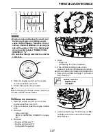
CHECKING THE FRONT BRAKE PADS
The following procedure applies to all of the
brake pads.
1. Operate the brake.
A. Front brake
B. Rear brake
Direction “b”
Brake lever distance “a” is increased.
Direction “c”
Brake lever distance “a” is decreased.
Summary of Contents for YZFR1Y(C) 2009
Page 1: ...SERVICE MANUAL YZFR1Y C 14B 28197 10 LIT 11616 22 78 2009 ...
Page 6: ......
Page 8: ......
Page 36: ...SPECIAL TOOLS 1 27 ...
Page 66: ...LUBRICATION SYSTEM CHART AND DIAGRAMS 2 29 EAS20410 LUBRICATION DIAGRAMS ...
Page 68: ...LUBRICATION SYSTEM CHART AND DIAGRAMS 2 31 ...
Page 70: ...LUBRICATION SYSTEM CHART AND DIAGRAMS 2 33 ...
Page 72: ...LUBRICATION SYSTEM CHART AND DIAGRAMS 2 35 ...
Page 73: ...LUBRICATION SYSTEM CHART AND DIAGRAMS 2 36 1 Main axle 2 Oil water pump assembly ...
Page 74: ...LUBRICATION SYSTEM CHART AND DIAGRAMS 2 37 ...
Page 75: ...LUBRICATION SYSTEM CHART AND DIAGRAMS 2 38 1 Main axle 2 Oil delivery pipe 2 3 Drive axle ...
Page 76: ...LUBRICATION SYSTEM CHART AND DIAGRAMS 2 39 ...
Page 78: ...LUBRICATION SYSTEM CHART AND DIAGRAMS 2 41 ...
Page 80: ...LUBRICATION SYSTEM CHART AND DIAGRAMS 2 43 ...
Page 81: ...LUBRICATION SYSTEM CHART AND DIAGRAMS 2 44 1 Balancer shaft 2 Crankshaft ...
Page 82: ...COOLING SYSTEM DIAGRAMS 2 45 EAS20420 COOLING SYSTEM DIAGRAMS ...
Page 84: ...COOLING SYSTEM DIAGRAMS 2 47 ...
Page 85: ...COOLING SYSTEM DIAGRAMS 2 48 1 Radiator cap 2 Radiator 3 Radiator fan 4 Oil cooler ...
Page 86: ...CABLE ROUTING 2 49 EAS20430 CABLE ROUTING ...
Page 88: ...CABLE ROUTING 2 51 ...
Page 90: ...CABLE ROUTING 2 53 ...
Page 92: ...CABLE ROUTING 2 55 ...
Page 94: ...CABLE ROUTING 2 57 ...
Page 96: ...CABLE ROUTING 2 59 ...
Page 98: ...CABLE ROUTING 2 61 ...
Page 100: ...CABLE ROUTING 2 63 ...
Page 102: ...CABLE ROUTING 2 65 ...
Page 104: ...CABLE ROUTING 2 67 ...
Page 106: ...CABLE ROUTING 2 69 ...
Page 108: ...CABLE ROUTING 2 71 ...
Page 110: ...CABLE ROUTING 2 73 ...
Page 113: ......
Page 148: ...PERIODIC MAINTENANCE 3 35 ...
Page 253: ...ENGINE REMOVAL 5 12 Installed depth of gasket c 3 5 mm 0 14 in ...
Page 286: ...PICKUP ROTOR 5 45 Yamaha bond No 1215 Three Bond No 1215 90890 85505 ...
Page 291: ...ELECTRIC STARTER 5 50 ...
Page 340: ...TRANSMISSION 5 99 ...
Page 356: ...WATER PUMP 6 15 ...
Page 378: ...AIR INDUCTION SYSTEM 7 21 EAS27040 AIR INDUCTION SYSTEM ...
Page 384: ...AIR INDUCTION SYSTEM 7 27 ...
Page 387: ......
Page 388: ...IGNITION SYSTEM 8 1 EAS27090 IGNITION SYSTEM EAS27110 CIRCUIT DIAGRAM ...
Page 394: ...ELECTRIC STARTING SYSTEM 8 7 EAS27160 ELECTRIC STARTING SYSTEM EAS27170 CIRCUIT DIAGRAM ...
Page 400: ...CHARGING SYSTEM 8 13 EAS27200 CHARGING SYSTEM EAS27210 CIRCUIT DIAGRAM ...
Page 403: ...CHARGING SYSTEM 8 16 ...
Page 404: ...LIGHTING SYSTEM 8 17 EAS27240 LIGHTING SYSTEM EAS27250 CIRCUIT DIAGRAM ...
Page 408: ...SIGNALING SYSTEM 8 21 EAS27270 SIGNALING SYSTEM EAS27280 CIRCUIT DIAGRAM ...
Page 415: ...SIGNALING SYSTEM 8 28 ...
Page 416: ...COOLING SYSTEM 8 29 EAS27300 COOLING SYSTEM EAS27310 CIRCUIT DIAGRAM ...
Page 419: ...COOLING SYSTEM 8 32 ...
Page 420: ...FUEL INJECTION SYSTEM 8 33 EAS27330 FUEL INJECTION SYSTEM EAS27340 CIRCUIT DIAGRAM ...
Page 484: ...FUEL PUMP SYSTEM 8 97 EAS27550 FUEL PUMP SYSTEM EAS27560 CIRCUIT DIAGRAM ...
Page 488: ...ELECTRICAL COMPONENTS 8 101 EAS27972 ELECTRICAL COMPONENTS ...
Page 490: ...ELECTRICAL COMPONENTS 8 103 ...
Page 492: ...ELECTRICAL COMPONENTS 8 105 EAS27980 CHECKING THE SWITCHES ...
Page 516: ...ELECTRICAL COMPONENTS 8 129 ...
Page 523: ......
Page 524: ...YAMAHA MOTOR CO LTD 2500 SHINGAI IWATA SHIZUOKA JAPAN ...
Page 525: ...WIRING DIAGRAM YZFR1Y C ...
Page 526: ...WIRING DIAGRAM YZFR1Y C ...


