CABLE ROUTING
2-68
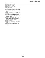
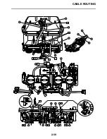
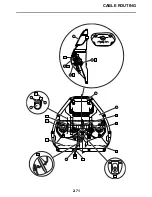
1. Fuel tank upper cover
2. Fuel tank breather hose
3. Fuel tank overflow hose
4. Fuel tank
5. Fuel pump
6. Frame
7. Fuel hose connector cover
8. Clip
9. Fuel hose
10.Rollover valve
11.Canister
12.Rollover valve hose
13.Canister bracket
14.Clamp
A. Install the lip on the fuel pump gasket
upward.
B. Pump positioning punch mark
C. Install the fuel pump with the pump posi-
tioning punch mark and fuel pump bracket
concave part at the same position.
D. Install the fuel tank overflow hose and fuel
tank breather hose with the white paint
mark on each hose facing right of the vehi-
cle.
E. Align the clip knob to the paint mark on
each hose and face it to right of the vehicle.
F. Align the clip knob to the paint mark on
each hose and face it to front of the vehi-
cle.
G. Install the fuel tank breather hose with its
white paint facing front of the vehicle.
H. Install the fuel tank overflow hose with its
yellow paint facing front of the vehicle.
I. Install the fuel tank overflow hose and fuel
tank breather hose with the clamp opening
facing down.
J. Fuel pump side
K. Insert the connector until the click sound is
heard and check that the connector does
not come off. Make sure that no foreign
matter is caught in the sealing section. (It is
prohibited to wear the cotton work gloves
or equivalent coverings.)
L. After item “K” mentioned above is finished,
check that the clamp is inserted from the
down side “a”, “b” and “c” sections are per-
fectly equipped.
M. This part works as a dropout stopper
N. Engine side
O. After Step “K” as above is finished, check
that the connector is completely attached
by sliding the double lock (orange part) “d”
on the connector as shown in the illustra-
tion and seeing if it touches firmly or not.
P. California only
Q. Face the clip’s knob upward.
R. Align the clip knob to the paint mark on
each hose and face it to left of the vehicle.
S. Install the canister hose with the 90
°
bent
hose to the canister side and about parallel
to the rollover valve.
T. To the throttle body
Summary of Contents for YZFR1Y(C) 2009
Page 1: ...SERVICE MANUAL YZFR1Y C 14B 28197 10 LIT 11616 22 78 2009 ...
Page 6: ......
Page 8: ......
Page 36: ...SPECIAL TOOLS 1 27 ...
Page 66: ...LUBRICATION SYSTEM CHART AND DIAGRAMS 2 29 EAS20410 LUBRICATION DIAGRAMS ...
Page 68: ...LUBRICATION SYSTEM CHART AND DIAGRAMS 2 31 ...
Page 70: ...LUBRICATION SYSTEM CHART AND DIAGRAMS 2 33 ...
Page 72: ...LUBRICATION SYSTEM CHART AND DIAGRAMS 2 35 ...
Page 73: ...LUBRICATION SYSTEM CHART AND DIAGRAMS 2 36 1 Main axle 2 Oil water pump assembly ...
Page 74: ...LUBRICATION SYSTEM CHART AND DIAGRAMS 2 37 ...
Page 75: ...LUBRICATION SYSTEM CHART AND DIAGRAMS 2 38 1 Main axle 2 Oil delivery pipe 2 3 Drive axle ...
Page 76: ...LUBRICATION SYSTEM CHART AND DIAGRAMS 2 39 ...
Page 78: ...LUBRICATION SYSTEM CHART AND DIAGRAMS 2 41 ...
Page 80: ...LUBRICATION SYSTEM CHART AND DIAGRAMS 2 43 ...
Page 81: ...LUBRICATION SYSTEM CHART AND DIAGRAMS 2 44 1 Balancer shaft 2 Crankshaft ...
Page 82: ...COOLING SYSTEM DIAGRAMS 2 45 EAS20420 COOLING SYSTEM DIAGRAMS ...
Page 84: ...COOLING SYSTEM DIAGRAMS 2 47 ...
Page 85: ...COOLING SYSTEM DIAGRAMS 2 48 1 Radiator cap 2 Radiator 3 Radiator fan 4 Oil cooler ...
Page 86: ...CABLE ROUTING 2 49 EAS20430 CABLE ROUTING ...
Page 88: ...CABLE ROUTING 2 51 ...
Page 90: ...CABLE ROUTING 2 53 ...
Page 92: ...CABLE ROUTING 2 55 ...
Page 94: ...CABLE ROUTING 2 57 ...
Page 96: ...CABLE ROUTING 2 59 ...
Page 98: ...CABLE ROUTING 2 61 ...
Page 100: ...CABLE ROUTING 2 63 ...
Page 102: ...CABLE ROUTING 2 65 ...
Page 104: ...CABLE ROUTING 2 67 ...
Page 106: ...CABLE ROUTING 2 69 ...
Page 108: ...CABLE ROUTING 2 71 ...
Page 110: ...CABLE ROUTING 2 73 ...
Page 113: ......
Page 148: ...PERIODIC MAINTENANCE 3 35 ...
Page 253: ...ENGINE REMOVAL 5 12 Installed depth of gasket c 3 5 mm 0 14 in ...
Page 286: ...PICKUP ROTOR 5 45 Yamaha bond No 1215 Three Bond No 1215 90890 85505 ...
Page 291: ...ELECTRIC STARTER 5 50 ...
Page 340: ...TRANSMISSION 5 99 ...
Page 356: ...WATER PUMP 6 15 ...
Page 378: ...AIR INDUCTION SYSTEM 7 21 EAS27040 AIR INDUCTION SYSTEM ...
Page 384: ...AIR INDUCTION SYSTEM 7 27 ...
Page 387: ......
Page 388: ...IGNITION SYSTEM 8 1 EAS27090 IGNITION SYSTEM EAS27110 CIRCUIT DIAGRAM ...
Page 394: ...ELECTRIC STARTING SYSTEM 8 7 EAS27160 ELECTRIC STARTING SYSTEM EAS27170 CIRCUIT DIAGRAM ...
Page 400: ...CHARGING SYSTEM 8 13 EAS27200 CHARGING SYSTEM EAS27210 CIRCUIT DIAGRAM ...
Page 403: ...CHARGING SYSTEM 8 16 ...
Page 404: ...LIGHTING SYSTEM 8 17 EAS27240 LIGHTING SYSTEM EAS27250 CIRCUIT DIAGRAM ...
Page 408: ...SIGNALING SYSTEM 8 21 EAS27270 SIGNALING SYSTEM EAS27280 CIRCUIT DIAGRAM ...
Page 415: ...SIGNALING SYSTEM 8 28 ...
Page 416: ...COOLING SYSTEM 8 29 EAS27300 COOLING SYSTEM EAS27310 CIRCUIT DIAGRAM ...
Page 419: ...COOLING SYSTEM 8 32 ...
Page 420: ...FUEL INJECTION SYSTEM 8 33 EAS27330 FUEL INJECTION SYSTEM EAS27340 CIRCUIT DIAGRAM ...
Page 484: ...FUEL PUMP SYSTEM 8 97 EAS27550 FUEL PUMP SYSTEM EAS27560 CIRCUIT DIAGRAM ...
Page 488: ...ELECTRICAL COMPONENTS 8 101 EAS27972 ELECTRICAL COMPONENTS ...
Page 490: ...ELECTRICAL COMPONENTS 8 103 ...
Page 492: ...ELECTRICAL COMPONENTS 8 105 EAS27980 CHECKING THE SWITCHES ...
Page 516: ...ELECTRICAL COMPONENTS 8 129 ...
Page 523: ......
Page 524: ...YAMAHA MOTOR CO LTD 2500 SHINGAI IWATA SHIZUOKA JAPAN ...
Page 525: ...WIRING DIAGRAM YZFR1Y C ...
Page 526: ...WIRING DIAGRAM YZFR1Y C ...


