


2-13
E
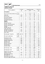
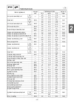
SPEC
Grommet bracket bolt
M6
8
0.8
5.9
5-80
Generator cover assembly bolt
M8
26
2.6
19.2
5-80
Transfer shaft
—
120
12.0
88.5
5-80
Flywheel magneto bolt
M8
24
2.4
17.7
5-80
Pickup coil bolt
M5
5
0.5
3.7
5-82
Washer bolt
M5
5
0.5
3.7
5-82
Stator coil assembly bolt
M6
15
1.5
11.1
5-82
Clamp bolt
M6
15
1.5
11.1
5-82
Thermoswitch bolt
M6
8
0.8
5.9
5-90
Knock sensor
—
15
1.5
11.1
5-90
Anode cover bolt
M8
20
2.0
14.8
5-90
Anode bolt
M6
8
0.8
5.9
5-90
Engine temperature sensor
—
15
1.5
11.1
5-90
Earth plate bolt
M6
8
0.8
5.9
5-90
Water jacket cover bolt
M6
8
0.8
5.9
5-90
Oil pressure switch lead bolt
M4
2
0.2
1.5
5-90
Oil pressure switch
—
8
0.8
5.9
5-90
Oil separator tank cover bolt
M6
8
0.8
5.9
5-90
Oil pan assembly bolt
M6
10
1.0
7.4
5-90
Baffle plate bolt
M6
12
1.2
8.9
5-94
Oil pipe 1 and 2 bolt
M6
9
0.9
6.6
5-94
Bracket 1 and 2 bolt
M10
50
5.0
36.9
5-96
Baffle plate bolt
M6
10
1.0
7.4
5-96
Crankcase bolt
M6
10
1.0
7.4
5-96
1st
M10
30
3.0
22.1
2nd
90
°
Connecting rod cap nut
1st
—
51
5.1
37.6
5-96
2nd
90
°
Thermostat housing bolt
M6
8
0.8
5.9
5-116
Jet pump unit
Intake grate bolt
M6
8
0.8
5.9
6-1
M8
17
1.7
12.5
Ride plate bolt
M8
17
1.7
12.5
6-1
Speed sensor screw (FX SHO)/Speed
and water temperature sensor screw
(FX Cruiser SHO)
M5
4
0.4
3.0
6-1
Steering cable joint nut
—
7
0.7
5.2
6-2
Spout hose clamp (hull end)
—
2
0.2
1.5
6-2
Rubber plate bolt
M6
7
0.7
5.2
6-2
Jet pump unit assembly bolt
M6
8
0.8
5.9
6-2
M10
40
4.0
29.5
Stay bolt
M8
15
1.5
11.1
6-2
Spout hose clamp (jet pump end)
—
1
0.1
0.7
6-6
Reverse gate assembly bolt
M8
20
2.0
14.8
6-6
Part to tightened
Thread
size
Tightening torque
Refer to
page
N
·
m
kgf
·
m
ft
·
lb
Summary of Contents for WaveRunner FX SHO
Page 1: ...SERVICE MANUAL FX SHO WaveRunner F1W 28197 1K 11 FX Cruiser SHO LIT 18616 03 12 LIT186160312 ...
Page 58: ...1 53 E GEN INFO MEMO Technical tips ...
Page 82: ...2 23 E SPEC MEMO Cable and hose routing ...
Page 110: ...3 27 E CHK ADJ MEMO General ...
Page 243: ...5 118 E POWR 1 2 3 4 5 6 7 8 9 MEMO Cooling water ...
Page 275: ...6 30 E JET PUMP 1 2 3 4 5 6 7 8 9 MEMO Intermediate housing ...
Page 353: ...E ELEC 1 2 3 4 5 6 7 8 9 7 76 MEMO Indication system ...
Page 410: ...8 55 E HULL HOOD MEMO Deck and hull ...
Page 429: ...9 18 E TRBL ANLS 1 2 3 4 5 6 7 8 9 MEMO Engine unit trouble analysis ...
Page 431: ......
Page 432: ...YAMAHA MOTOR CORPORATION USA Printed in USA Jan 2008 0 0 1 CR E ...


