


6-4
E
JET
PUMP
1
2
3
4
5
6
7
8
9
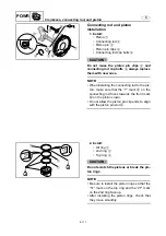
Jet pump unit removal
WARNING
Be sure to remove the battery before re-
moving the jet pump unit.
1. Remove:
•
Intake grate
1
•
Speed sensor
2
(FX SHO)
Speed and water temperature sensor
2
(FX Cruiser SHO)
•
Ride plate
3
2
1
3
2. Remove:
•
Steering cable joint
1
•
Shift cable joint
2
•
QSTS rod joint
3
•
Spout hose
4
•
Rubber plats
5
2
1
3
5
4
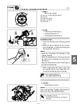
3. Remove:
•
Bolt (M6
×
30 mm)
1
•
Bolts (M10
×
45 mm)
2
1
2
2
4. Remove:
•
Jet pump unit
1
NOTE:
Insert a flat-head screwdriver into the gap
a
between the jet pump unit
1
and the transom
plate
2
to separate them.
2
1
a
Summary of Contents for WaveRunner FX SHO
Page 1: ...SERVICE MANUAL FX SHO WaveRunner F1W 28197 1K 11 FX Cruiser SHO LIT 18616 03 12 LIT186160312 ...
Page 58: ...1 53 E GEN INFO MEMO Technical tips ...
Page 82: ...2 23 E SPEC MEMO Cable and hose routing ...
Page 110: ...3 27 E CHK ADJ MEMO General ...
Page 243: ...5 118 E POWR 1 2 3 4 5 6 7 8 9 MEMO Cooling water ...
Page 275: ...6 30 E JET PUMP 1 2 3 4 5 6 7 8 9 MEMO Intermediate housing ...
Page 353: ...E ELEC 1 2 3 4 5 6 7 8 9 7 76 MEMO Indication system ...
Page 410: ...8 55 E HULL HOOD MEMO Deck and hull ...
Page 429: ...9 18 E TRBL ANLS 1 2 3 4 5 6 7 8 9 MEMO Engine unit trouble analysis ...
Page 431: ......
Page 432: ...YAMAHA MOTOR CORPORATION USA Printed in USA Jan 2008 0 0 1 CR E ...


