background image

30

Basic operation

—Owner’s Manual

Overdubbing

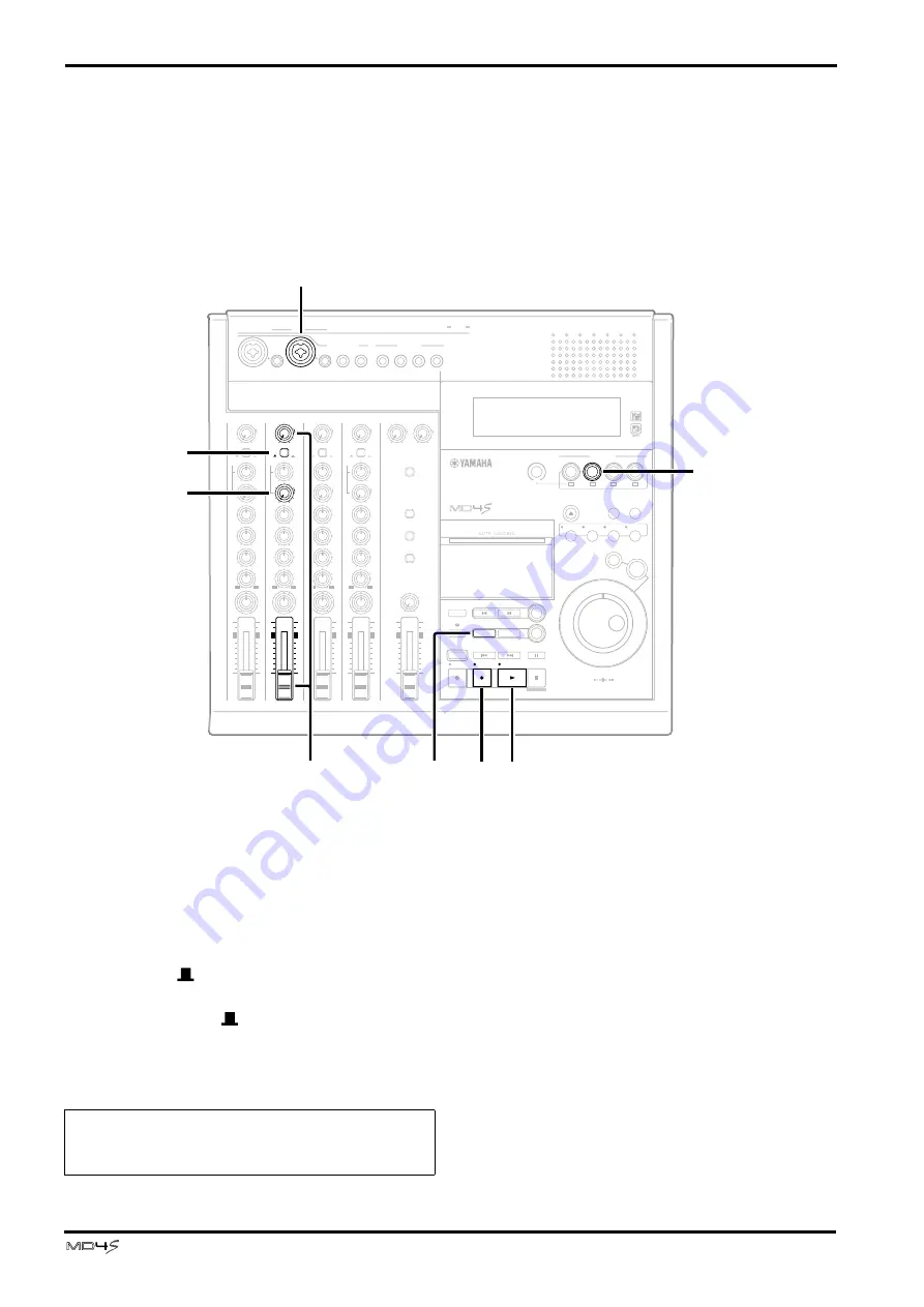
Now that you have finished recording track 1, let’s record additional audio sources on other 
tracks while listening to the playback of this track. The basic procedure is the same as in 
“Recording the first track.”

Select the track to record

1

Connect the audio source to MIC/LINE 
INPUT jack 2.

2

Set the input channel 2 FLIP switch to the 
MIC/LINE (

) position.

At this time, leave the input channel 1 FLIP switch 
in the MIC/LINE (

) position.

3

Press REC SELECT button 2.

The track 2 track record indicator (DIR) will 
blink, and track 2 will be ready to record.

4

Press the REC button to enter record-pause 
mode.

5

While watching the track level meter, use the 
GAIN control and fader of input channel 2 to 
set the recording level.

L

R

L

R

5 / 6

7 / 8

STEREO

MONITOR LEVEL

CUE

STEREO

2TR IN

CUE MIX TO STEREO

MONITOR SELECT

10

9

8

7

6

5

4

3

2

1

0

10

9

8

7

6

5

4

3

2

1

0

TOC WRITE

REHE

STOP

PAUSE

OUT

SONG SEARCH

MARK SEARCH

REPEAT

AUTO

PUNCH I/O

A

B

DATA

CURSOR

PHONES

PUNCH I/O

PITCH

EJECT

ADJUST

EDIT

UTILITY

CH1

BUS

REC SELECT

CH3

CH4

PEAK HOLD

DISPLAY

0

10

0

10

MIN

MAX

MULTITRACK MD RECORDER

IN

THRU

OUT
MIDI

MIC/LINE INPUT

3

1

4

5

6

7

8

LINE INPUT

AUX SEND

INSERT

I/O

INSERT

I/O

TRACK

DIRECT OUT

STEREO

OUT

2TR IN

MONITOR

OUT

1

2

EXIT

ENTER

SET

MARK

1

1

4

4

GAIN

CUE

HIGH

LINE

FLIP

MIC/
LINE

MIC

L

R

0

10

–15

+15

MID

–15

+15

LOW

–15

+15

PAN

L

R

AUX

1

2

PB

10

9

8

7

6

5

4

3

2

1

0

P

A

N

L

E

V

E

L

3

3

GAIN

CUE

HIGH

LINE

FLIP

MIC/
LINE

MIC

L

R

0

10

–15

+15

MID

–15

+15

LOW

–15

+15

PAN

L

R

AUX

1

2

PB

10

9

8

7

6

5

4

3

2

1

0

P

A

N

L

E

V

E

L

2

2

CUE

HIGH

L

R

–15

+15

MID

–15

+15

LOW

–15

+15

PAN

L

R

AUX

1

2

P

A

N

GAIN

CUE

HIGH

LINE

FLIP

MIC/
LINE

MIC

L

R

0

10

–15

+15

MID

–15

+15

LOW

–15

+15

PAN

L

R

AUX

1

2

PB

10

9

8

7

6

5

4

3

2

1

0

P

A

N

L

E

V

E

L

1

4

3

REC

PLAY

IN

LAST REC SEARCH

CH2

2

10

9

8

7

6

5

4

3

2

1

0

GAIN

LINE

FLIP

MIC/
LINE

MIC

0

10

PB

L

E

V

E

L

2

2

6

4 7

9

8

5

1

30

Note:   You must make sure that the track 1 record 
indicator (DIR) is dark. If it is blinking, press REC 
SELECT button 1.

Summary of Contents for MD4S

Page 1: ... 4 5 6 7 8 LINE INPUT AUX SEND INSERT I O INSERT I O TRACK DIRECT OUT STEREO OUT 2TR IN MONITOR OUT 1 2 1 2 3 4 EXIT ENTER SET MARK 1 1 GAIN CUE HIGH LINE FLIP MIC LINE MIC L R 0 10 15 15 MID 15 15 LOW 15 15 PAN L R AUX 1 2 PB 10 9 8 7 6 5 4 3 2 1 0 P A N L E V E L 2 2 GAIN CUE HIGH LINE FLIP MIC LINE MIC L R 0 10 15 15 MID 15 15 LOW 15 15 PAN L R AUX 1 2 PB 10 9 8 7 6 5 4 3 2 1 0 P A N L E V E L ...

Page 2: ...he letter L or coloured RED Making sure that neither core is connected to the earth terminal of the three pin plug This applies only to products distributed by YAMAHA KEMBLE MUSIC U K LTD FCC INFORMATION U S A 1 IMPORTANT NOTICE DO NOT MODIFY THIS UNIT This product when installed as indicated in the instructions contained in this manual meets FCC requirements Modifications not expressly approved b...

Page 3: ...performance or E The appliance has been dropped or the enclosure dam aged 17 Servicing The user should not attempt service the appliance beyond that described in the operating instructions SAFETY INSTRUCTIONS CAUTION TO REDUCE THE RISK OF ELECTRIC SHOCK DO NOT REMOVE COVER OR BACK NO USER SERVICEABLE PARTS INSIDE REFER SERVICING TO QUALIFIED SERVICE PERSONNEL CAUTION RISK OF ELECTRIC SHOCK DO NOT ...

Page 4: ...ing the unit without heeding this instruction fire or electrical shock may result If the power cord is damaged i e cut or a bare wire is exposed ask your dealer for a replacement Using the unit with a damaged power cord is a fire and electrical shock hazard Do not remove the unit s cover You could receive an electrical shock If you think internal inspection maintenance or repair is necessary conta...

Page 5: ...by radios and TVs If noise occurs relocate the affected equipment XLR type connectors are wired as follows pin 1 ground pin 2 hot and pin 3 cold Insert TRS phone jacks are wired as follows sleeve ground tip send and ring return The performance of components with moving contacts such as switches rotary controls faders and connectors deteriorates over time The rate of deterioration depends on the op...

Page 6: ... Disc transport section 16 Display 19 Top panel connectors 22 Rear panel 23 Front panel 24 Basic operation 25 Before you begin 25 Example connections 25 Turning on the MD4S 26 Inserting a disc 26 Recording the first track Direct Recording 26 Preparations for recording 26 Start recording 28 Overdubbing 30 Mixdown 32 After completing the Basic Operation section 34 Advanced recording techniques 35 Ad...

Page 7: ...g playback order Program Play 71 Editing functions 73 Copying a portion of a track Part Copy 73 Erasing a section of a track Part Erase 74 Copying an entire track to another track Track Copy 75 Erasing an entire track Track Erase 76 Copying converting a song Song Copy 76 Erasing a song Song Erase 78 Splitting a song into two Song Divide 79 Joining divided songs together Song Combine 80 Moving a so...

Page 8: ...Section 100 Troubleshooting 101 Display Messages 103 Modes of the MD4S transport 104 Specifications 105 Recorder 105 Mixer 105 General 106 Dimensions 106 Block Diagram 107 Glossary 108 Tempo Map Chart 111 MIDI Implementation Chart 112 Index 113 ...

Page 9: ...ht sources including track playback signals can be mixed TRACK DIRECT OUT jacks are provided for direct output of the playback from each track Recorder The recorder features a 4 track recorder based on the MD DATA audio format This provides many advantages over tape based multitrack recorders You can choose from three recording modes 4 track 2 track monaural Negligible decrease in audio quality ev...

Page 10: ...is type of disc MiniDiscs also known as MD are used only for music Type MD DATA MiniDisc Logo 4 track recording playback Yes 37 minutes per track No 2 track recording playback Yes 74 minutes Yes 74 minutes Monaural recording playback Yes 148 minutes Yes 148 minutes Notes These discs are for computer stor age applications and can be pur chased at computer shops Two types are available playback only...

Page 11: ...TE button are the same button The display will show Writing TOC indicating that the TOC is being written to disc When the TOC has been updated the Writing TOC display and the TOC EDIT indicator will go dark Recording modes and recording times The MD4S offers three recording modes 4 track 4TR 2 track 2TR and monaural MONO The times available for recording on a single disc will depend on the recordi...

Page 12: ...k area immediately after song 1 it is not immediately possible to record additional material to song 1 to lengthen it If three songs songs 1 2 and 3 are recorded consecutively on disc as shown in the following diagram and the middle song is erased there will be a blank area corresponding to the length of that song Blank areas are also assigned a blank area number in the order in which they are cre...

Page 13: ...eing recorded or played back will be sent to the CUE bus When this switch is in the PB position the signal from the track will be sent to the input channel and the signal from the MIC LINE jack will be sent to the CUE bus 1 1 GAIN CUE HIGH LINE FLIP MIC LINE MIC L R 0 10 15 15 MID 15 15 LOW 15 15 PAN L R AUX 1 2 PB 10 9 8 7 6 5 4 3 2 1 0 P A N L E V E L 1 2 5 6 7 3 4 GAIN HIGH LINE MIC 15 15 MID 1...

Page 14: ...lly used to adjust the signal level that is sent to external effect devices F PAN control This control adjusts the pan left right position of the input channel signal that is sent to the ST bus If you are recording via the ST bus rotating this control to the L position will assign the input signal to odd numbered tracks tracks 1 and 3 and rotating it to the R position will assign the input signal ...

Page 15: ...cks rear panel 4 and the PHONES jack front panel 1 When the switch is pressed in the corresponding source is selected on When the switch is up the signal will not be selected off The three switches can be turned on off independently 2TR IN Monitor the signal that is input from the 2TR IN jacks rear panel 6 STEREO Monitor the ST bus signal that is output from the STEREO OUT jacks rear panel 5 CUE M...

Page 16: ...ou press the PLAY button without pressing the REHE or REC button normal playback will begin During playback recording rehearsal the PLAY indicator located above the button will light When playback recording rehearsal is paused the PLAY indicator will blink PAUSE button This button temporarily halts pauses playback recording rehearsal After operation has been paused pressing the PAUSE button once a...

Page 17: ...repeat function on off The repeat indicator display O will light to indicate the repeat function that is selected G MARK SEARCH MARK buttons The MARK SEARCH buttons are used to locate to the Start marker beginning of the song End marker end of the song or to markers that you can set at desired locations in the song The MARK button is used to insert a marker into the desired location of a song H Di...

Page 18: ...cording to the setting the pitch indicator in the display will indicate FIX fixed or VARI variable ADJUST button Allows you to make fine adjustments to the markers or last recording in out points that you have set within a song page 63 EDIT button Accesses a variety of editing functions and allows you to specify a disc title or song title UTILITY button Allows you to use MIDI functions adjust the ...

Page 19: ...ion is on FIX Lights when the Pitch function is off VARI Lights when the Pitch function is on D Title and function display Song numbers song disc titles the currently selected function or other messages will appear here Indicator Meaning Normal playback Cue or Review Playback is paused Rehearsal Pause mode Rehearsal in progress Record Pause mode Recording in progress 1 2 3 4 5 6 7 8 9 OUT IN E 10 ...

Page 20: ...C This will light when you enable MMC MIDI Machine Control reception In this case the MD4S can be controlled from an external device such as a MIDI sequencer G Track level meters These indicate the recording playback level of each track The range from 39 dB to CLIP is shown in nine steps The CLIP indicator will light to indicate that digital clipping has occurred in the signal If no disc is insert...

Page 21: ...dark when the song reaches or passes the specified OUT point M Time counter This indicates time locations on the disc in minutes seconds frames When transmitting MIDI Clock data the minutes seconds frames display can be changed to measures beats clocks In this case the MEASURE and BEAT indicators will light N Marker indicators These indicate the status of the various markers that have been set wit...

Page 22: ... as a compressor or noise gate to these jacks you can process the signal of input channels 1 and 2 C MIC LINE INPUT 3 4 jacks These are 1 4 phone jacks used to connect electronic instruments such as a synthesizer or an unbalanced mic D LINE INPUT 5 8 jacks These are 1 4 phone jacks used to connect line level devices such as synthesizers or CD players They can also be used as effect return jacks to...

Page 23: ...he signal of the ST bus that has passed through the STEREO fader monitor master L During mixdown connect these jacks to the inputs of your master recorder F 2TR IN jacks These are RCA phono jacks for connecting a line level stereo device Normally they are connected to the output jacks of your DAT or other master recorder G TRACK DIRECT OUT 1 4 jacks These are RCA phono jacks which individually out...

Page 24: ...when controlling the transport of the MD4S from an external MIDI sequencer MIDI THRU connector MIDI messages received at the MIDI IN connector are retransmitted without change from this connector to another external MIDI device Front panel A PHONES jack A pair of stereo headphones can be connected here for monitoring This jack will output the same signal as the MONITOR OUT jacks B PUNCH I O jack A...

Page 25: ...INE INPUT 3 2 1 4 5 6 7 8 LINE INPUT AUX SEND INSERT I O INSERT I O TRACK DIRECT OUT STEREO OUT 2TR IN MONITOR OUT 1 2 1 2 3 4 EXIT ENTER SET MARK 1 1 GAIN CUE HIGH LINE FLIP MIC LINE MIC L R 0 10 15 15 MID 15 15 LOW 15 15 PAN L R AUX 1 2 PB 10 9 8 7 6 5 4 3 2 1 0 P A N L E V E L 2 2 GAIN CUE HIGH LINE FLIP MIC LINE MIC L R 0 10 15 15 MID 15 15 LOW 15 15 PAN L R AUX 1 2 PB 10 9 8 7 6 5 4 3 2 1 0 P...

Page 26: ...or to MIC LINE INPUT jack 3 if you wish to record on track 3 this method is convenient when you will be recording each part separately In this example we will explain how to record your first audio source on track 1 Preparations for recording L R L R 5 6 7 8 STEREO STEREO 2TR IN CUE MIX TO STEREO MONITOR SELECT 10 9 8 7 6 5 4 3 2 1 0 10 9 8 7 6 5 4 3 2 1 0 TOC WRITE REHE PLAY STOP PAUSE IN OUT LAS...

Page 27: ... will be in record pause mode The display will indicate the number of the song to be recorded 001 and if this is the first time you are recording the song the display will indicate NEW REC 6 Rotate the GAIN control of input channel 1 all the way to the LINE position 7 Set the input channel 1 fader between the 7 and 8 marks 8 While playing your audio source watch the track level meter and rotate th...

Page 28: ...ll change from blinking to lit Begin playing the audio source that you wish to record first 3 When you finish recording press the STOP button The transport will stop and the track record indi cator of track 1 will change to blinking The display will indicate Writing TOC for a short time and then the TOC EDIT indicator will go dark indicating that the TOC has been updated automatically L R L R 5 6 ...

Page 29: ...r MONITOR OUT jacks If you decide to re record this take press the LAST REC SEARCH IN button and repeat steps 1 4 If you wish to re record just a portion of the track you can use punch in out See Punch in out on page 52 for more information 6 If you are satisfied with the recording on track 1 press the REC SELECT switch The track 1 track record indicator DIR will go dark Signal flow during track r...

Page 30: ...WRITE REHE STOP PAUSE OUT SONG SEARCH MARK SEARCH REPEAT AUTO PUNCH I O A B DATA CURSOR PHONES PUNCH I O PITCH EJECT ADJUST EDIT UTILITY CH1 BUS REC SELECT CH3 CH4 PEAK HOLD DISPLAY 0 10 0 10 MIN MAX MULTITRACK MD RECORDER IN THRU OUT MIDI MIC LINE INPUT 3 1 4 5 6 7 8 LINE INPUT AUX SEND INSERT I O INSERT I O TRACK DIRECT OUT STEREO OUT 2TR IN MONITOR OUT 1 2 EXIT ENTER SET MARK 1 1 4 4 GAIN CUE H...

Page 31: ...s the STOP but ton Listen to the recording 8 Press the LAST REC SEARCH IN button to move to the location where you began recording track 2 If you wish to start listening from the beginning of the song press the SONG SEARCH button 9 Press the PLAY button to playback and listen to the recording 0 If you are satisfied with the recording press the REC SELECT 2 button The track 2 track recording indica...

Page 32: ...e SONG SEARCH button to locate to the beginning of the song the start point and press the PLAY button to begin playback L R L R 5 6 7 8 MONITOR LEVEL CUE STEREO 2TR IN CUE MIX TO STEREO MONITOR SELECT REHE REC PAUSE IN OUT LAST REC SEARCH MARK SEARCH REPEAT AUTO PUNCH I O A B DATA CURSOR PHONES PUNCH I O PITCH EJECT ADJUST EDIT UTILITY CH1 BUS CH2 REC SELECT CH3 CH4 PEAK HOLD DISPLAY 0 10 0 10 MIN...

Page 33: ...ording 9 Press the MONITOR SELECT 2TR IN switch Now the playback of your master recorder that is being sent to the 2TR IN jacks will be sent to the PHONES jack and the MONITOR OUT jacks 0 Playback your master recorder from the beginning of the song and listen to the mas ter recording Use the MONITOR LEVEL control to adjust the monitor level Signal flow during mixdown STEREO 10 9 8 7 6 5 4 3 2 1 0 ...

Page 34: ...ster recorder However by taking full advantage of the functionality that the MD4S provides you can use more sophisticated recording methods and editing techniques The following page Advanced techniques on the MD4S introduces the wide variety of functionality provided by the MD4S You can look through the list to find a topic in which you are especially interested and continue reading from the appro...

Page 35: ...ome familiar with these advanced techniques so that you can enjoy the full potential of the MD4S Record a greater number of parts Mixing multiple channels as you record page 36 Ping pong recording page 39 Adding sounds during mixdown page 42 Apply effects while you record mixdown Applying effects page 44 Re record over a mistake Punch in out page 52 Jump immediately to a specific location in a son...

Page 36: ... PAUSE OUT SONG SEARCH MARK SEARCH REPEAT AUTO PUNCH I O A B DATA CURSOR PHONES PUNCH I O PITCH EJECT ADJUST EDIT UTILITY PEAK HOLD DISPLAY 0 10 0 10 MIN MAX MULTITRACK MD RECORDER IN THRU OUT MIDI 5 6 7 8 LINE INPUT AUX SEND INSERT I O INSERT I O TRACK DIRECT OUT STEREO OUT 2TR IN MONITOR OUT 1 2 EXIT ENTER SET MARK 1 1 4 4 CUE HIGH L R 0 10 15 15 MID 15 15 LOW 15 15 AUX 1 2 P A N L E V E L 3 CUE...

Page 37: ...ch 8 Set the CUE LEVEL controls of input channels 1 and 2 to the 7 8 range This allows the recording source for tracks 1 and 2 in this case the signals from input channels 1 4 be monitored in the CUE bus 9 Rotate the CUE PAN controls of input chan nels 1 and 2 to far left and far right respec tively This makes the CUE bus signal stereo and allows you to monitor the same sound image as is being rec...

Page 38: ...5 15 MID 15 15 LOW 15 15 PAN L R AUX 1 2 PB 10 9 8 7 6 5 4 3 2 1 0 P A N L E V E L 3 3 GAIN CUE HIGH LINE FLIP MIC LINE MIC L R 0 10 15 15 MID 15 15 LOW 15 15 PAN L R AUX 1 2 PB 10 9 8 7 6 5 4 3 2 1 0 P A N L E V E L 4 4 GAIN CUE HIGH LINE FLIP MIC LINE MIC L R 0 10 15 15 MID 15 15 LOW 15 15 PAN L R AUX 1 2 PB 10 9 8 7 6 5 4 3 2 1 0 P A N L E V E L STEREO 10 9 8 7 6 5 4 3 2 1 0 10 9 8 7 6 5 4 3 2 ...

Page 39: ...igital form repeated ping pong recording as shown above will not impair the audio quality However please be aware that since the MD4S s mixer section is analog repeated ping pong recording will result in a very small decrease in audio quality although compared to the result of ping pong recording on a tape MTR this loss will be virtually undetectable Tip If you ping pong record tracks 1 4 to track...

Page 40: ...racks 3 and 4 as you adjust the STEREO fader to set the recording level At the ideal level the 3 segment of the meter will light at the peaks L R 5 6 7 8 MONITOR LEVEL CUE 2TR IN CUE MIX TO STEREO MONITOR SELECT REHE PAUSE OUT MARK SEARCH REPEAT AUTO PUNCH I O A B DATA CURSOR PHONES PUNCH I O PITCH EJECT ADJUST EDIT UTILITY CH1 CH2 REC SELECT PEAK HOLD DISPLAY 0 10 0 10 MIN MAX MULTITRACK MD RECOR...

Page 41: ...oint at which ping pong recording began and while using the MONI TOR LEVEL control to adjust the monitor level listen to the recorded content of tracks 3 and 4 Signal flow for ping pong recording STEREO 10 9 8 7 6 5 4 3 2 1 0 10 9 8 7 6 5 4 3 2 1 0 1 1 GAIN CUE HIGH LINE FLIP MIC LINE MIC L R 0 10 15 15 MID 15 15 LOW 15 15 PAN L R AUX 1 2 PB 10 9 8 7 6 5 4 3 2 1 0 P A N L E V E L 2 2 GAIN CUE HIGH...

Page 42: ... will be sent via the CUE PAN LEVEL controls of input channels 1 and 2 to the CUE bus MD4S Track 1 Track 2 Track 3 Track 4 Stereo mix Drums Guitar Bass Vocal Master recorder External audio source L R L R 5 6 7 8 STEREO MONITOR LEVEL CUE STEREO 2TR IN MONITOR SELECT 10 9 8 7 6 5 4 3 2 1 0 10 9 8 7 6 5 4 3 2 1 0 TOC WRITE REHE REC STOP PAUSE IN OUT SONG SEARCH LAST REC SEARCH MARK SEARCH REPEAT AUTO...

Page 43: ... LINE INPUT jacks 1 and 2 start recording on your master recorder and play back the MD4S from the beginning of the song When recording is completed playback the master recorder to hear the recorded result Signal flow when adding external signals during mixdown Tip The input signals from LINE INPUT jacks 5 8 can be added to the mix during mixdown However since LINE INPUT jacks 5 6 and 7 8 are stere...

Page 44: ...fect only to a specific channel track as you record a track or while you mixdown Normally the technique of applying an effect via the INSERT I O jack is used for effects which affect the dynamics or tone of the original sound e g compressor limiter noise gate equalizer etc The INSERT I O jacks accommodate TRS tip ring sleeve phone plugs The signal of the input channel is sent from the tip of the I...

Page 45: ... track 1 or 2 HIGH 0 10 15 15 MID 15 15 LOW 15 15 PAN L R AUX 1 2 10 9 8 7 6 5 4 3 2 1 0 INSERT I O Sleeve Tip Sleeve Ring Tip Input jack of the external effect processor Output jack of the external effect processor INSERT I O jack 5 6 7 8 2TR IN CUE MIX TO STEREO MONITOR SELECT PITCH EJECT ADJUST EDIT UTILITY CH1 BUS CH2 REC SELECT CH3 CH4 L R L R PEAK HOLD DISPLAY 0 10 0 10 MULTITRACK MD RECORDE...

Page 46: ...END jacks to apply effects is used for effects in which the original sound is mixed with the processed sound e g delay reverb chorus etc In general you should make settings on the effect processor so that it will output only the processed sound and use the MD4S mixer to adjust the mix of the original sound the signal sent from the input channel to the ST bus and the effect sound the signal sent vi...

Page 47: ...al effect processor will be mixed into the ST bus Raising the level control will increase the overall effect 5 When you are finished adjusting the effect depth press the SONG SEARCH button to locate to the beginning of the song and begin the mixdown L R L R 7 8 STEREO MONITOR LEVEL CUE STEREO 2TR IN CUE MIX TO STEREO MONITOR SELECT 10 9 8 7 6 5 4 3 2 1 0 10 9 8 7 6 5 4 3 2 1 0 TOC WRITE REHE REC S...

Page 48: ...AN controls to adjust the mix balance of tracks 1 4 If necessary use the EQ controls to adjust the tone When you have finished adjusting the mix bal ance watch the track 3 and 4 track level meters as you make fine adjustments to the STEREO fader to set the recording level At the ideal level the 3 segment will light when peaks occur 1 2 L R 7 8 MONITOR LEVEL CUE 2TR IN CUE MIX TO STEREO MONITOR SEL...

Page 49: ...l and will be sent via the AUX SEND 1 jack to the external effect processor 9 Raise level control 5 6 The effect sound from the external effect proces sor will be sent via LINE INPUT jacks 5 and 6 and mixed into the ST bus 0 When you have finished adjusting the mix balance recording level and effect amount press the SONG SEARCH button to locate to the beginning of the song and then press the REC b...

Page 50: ...gnal will be sent to the effect processor connected to the AUX SEND 1 jack 7 Raise level control 5 6 Only the vocal effect sound will be sent to the ST bus 8 Turn on the MONITOR SELECT CUE switch and MONITOR SELECT STEREO switch With these settings the signal of the CUE bus the playback of tracks 1 3 and the unprocessed vocal and the signal of the ST bus vocal effect sound can be monitored togethe...

Page 51: ... 1 2 PB 10 9 8 7 6 5 4 3 2 1 0 P A N L E V E L 3 3 GAIN CUE HIGH LINE FLIP MIC LINE MIC L R 0 10 15 15 MID 15 15 LOW 15 15 PAN L R AUX 1 2 PB 10 9 8 7 6 5 4 3 2 1 0 P A N L E V E L 4 4 GAIN CUE HIGH LINE FLIP MIC LINE MIC L R 0 10 15 15 MID 15 15 LOW 15 15 PAN L R AUX 1 2 PB 10 9 8 7 6 5 4 3 2 1 0 P A N L E V E L STEREO 10 9 8 7 6 5 4 3 2 1 0 10 9 8 7 6 5 4 3 2 1 0 5 6 0 10 5 4 6 R L MONITOR OUT P...

Page 52: ...erform manual punch in out Punch in out using the REC button 1 Connect the audio source to the MD4S 2 Set the FLIP switches of input channels 1 4 to MIC LINE 3 Turn on the MONITOR SELECT CUE switch When performing punch in out you will need to monitor the track playback up to the point where you punch in and monitor the recording source after punch in For this reason when you use punch in out you ...

Page 53: ...ed in step 1 press the REC SELECT but ton once again so that all track record indicators are dark 3 Press the PLAY button With the REC indicator still blinking the track will playback Recording will not occur at this time because the recording track is not selected 4 When you arrive at the location where you wish to punch in press the REC SELECT button for the track that you wish to record Alterna...

Page 54: ... 2 Press the foot switch The REC indicator will continue blinking and track playback will begin 3 Press the foot switch at the location where you wish to punch in The REC indicator and the track record indicator will change to steadily lit and recording will begin on the track selected by the REC SELECT button 4 Press the foot switch at the location where you wish to punch out The REC indicator wi...

Page 55: ...on and press the LAST REC SEARCH OUT button The display will indicate MARK OUT and this location will be specified as the auto punch out point Setting the pre roll post roll times Pre roll time is the length of playback that will occur immediately before the punch in point Post roll time is the length of playback that will occur immediately after the punch out point On the MD4S the pre roll and po...

Page 56: ...ormed only once and mult take in which punch in out can be performed two or more times after which you can select the best take Here we will explain the procedure for single take auto punch in out 1 Connect the audio source to the MD4S and press the REC SELECT button or the BUS button REC SELECT button to select the track that you wish to record 2 Set the auto punch in out points See Specify the a...

Page 57: ...unch in out When you press the PLAY button the MD4S will automatically locate to the pre roll point and begin playback When you reach the auto punch in point the IN indicator of the display will go dark and the track selected by the REC SELECT buttons will begin recording punch in When you reach the auto punch out point the OUT indicator of the display will go dark recording will end and playback ...

Page 58: ...The display will indicate TAKE 1 Load for a short time Then the AUTO PUNCH MULTI indicator will light indicating that multi take auto punch in out has been selected The dis play will indicate TAKE 1 Rehe and the MD4S will be in auto punch in out rehearsal pause mode Rehearsing the auto punch in out multi take 6 Press the PLAY button to begin rehearsing the auto punch in out In the same way as in s...

Page 59: ...e If you wish to listen to the takes that you have recorded advance to the following procedure with NEXT TAKE still displayed Auditioning each take 11 When you have finished recording auto punch in out takes and the display indicates NEXT TAKE rotate the DATA dial to make the display read MONI TAKE 12 Press the ENTER button The display will indicate TAKE X MONI X will be the take number 13 Rotate ...

Page 60: ...NTER button The display will ask FIX TAKE X If at this time you press the EXIT button you will again return to the step of selecting a take 18 Press the ENTER button once again to finalize the take When you finalize the take the display will indicate TAKE X FIX for a short time Then you will exit auto punch in out and return to normal operation ...

Page 61: ...ure beat clock location 1 Press the STOP or PAUSE button to stop or playback pause the MD4S It is not possible to locate to a specified time during playback or recording 2 Press the DISPLAY button to switch the time counter mode If you wish to locate to a point within the current song select ELAPSE TIME or REMAIN TIME If you wish to locate to a point within the entire disc select TOTAL TIME If a t...

Page 62: ... used as the auto punch in out points and to specify the range of various editing functions These points can be adjusted in steps of a single frame 11 6 ms For details refer to page 63 Searching for Markers The MD4S lets you place up to ten markers in each song You can use the MARK SEARCH button to locate immediately to markers that you inserted Markers are especially convenient when you need to r...

Page 63: ... mode 1 Press a MARK SEARCH button or a LAST REC SEARCH button to locate to the marker or auto punch in out point whose location you wish to adjust 2 Press the ADJUST button If you pressed a MARK SEARCH button in step 1 the display will indicate MARK X ADJST X will be the number of the marker that you selected and MARK X will be blinking If you pressed a LAST REC SEARCH button the display will ind...

Page 64: ...s between the first 1 5 seconds and the last 1 5 seconds If the display indicates the first 1 5 seconds will be played at a lower volume if the display indicates the last 1 5 seconds will be played at a lower volume 6 When you have finished making adjustments press the ENTER button The new location will be finalized and the MD4S will locate to that spot The display will return to the state in whic...

Page 65: ...ber By pressing the EXIT button at this point you can cancel the Erase operation 6 Press the ENTER button once again to erase the marker or press the EXIT but ton to cancel the Erase operation The marker indicator or IN OUT indicator that corresponds to the erased marker or auto punch in out point will go dark Depending on the marker that was erased the marker num bers will change 7 Press the ADJU...

Page 66: ...le When you press the PLAY button cue review will be canceled and normal playback will resume from that location If cue review reaches the beginning or end of the song it will stop Note It is not possible to move directly from normal playback to 1 2X speed cue You must move the CURSOR shuttle toward the right to select 2X cue or faster and then return the CURSOR shuttle to the 1 2X speed cue posit...

Page 67: ...le song to playback repeatedly The All Songs Repeat function causes all songs on the disc to playback repeatedly These functions can be selected when the MD4S is playing stopped or paused Note however that the One Song Repeat All Songs Repeat functions are disabled for MIDI sync operation In this case you can use the One Song Repeat function only on the MD4S that has been assigned as the MTC maste...

Page 68: ...point A and will begin playing repeatedly between points A and B 3 During A B Repeat press the REPEAT button to turn off the A B Repeat func tion A B Repeat will also be canceled if you press the STOP button Cue List playback Cue List is a function that lets you playback sections between markers in an order that you specify You can set up to 26 steps A Z each specifying the marker at which playbac...

Page 69: ... MD4S will be in Cue List playback pause mode During cue list playback the steps will be shown as uppercase letters A Z At this time you can rotate the DATA dial to change the step at which cue list playback will begin 8 Press the PLAY button to begin Cue List playback When all steps have finished playing back cue list playback will be canceled and the MD4S will stop If you wish to stop cue list p...

Page 70: ...ed you can cancel the Cue List Copy operation When the cue list copy has been completed the TOC will be updated automatically and the MD4S will stop at the beginning of the new song Note In rare circumstances playback may skip between steps of Cue List playback Note Cue List program contents are remembered even when the MD4S is turned off Cue List Original song New song after Cue List Copy a s 1 n...

Page 71: ... step The blinking character is the currently selected parameter 5 Rotate the CURSOR shuttle to select parameters and rotate the DATA dial to modify the value The range of each parameter is as follows Step number S1 S36 S will be displayed as a lowercase letter during programming Song number song number indicates that no song number has been specified for this step Note For steps 2 and following t...

Page 72: ...nge the step at which Program Play will begin 7 Press the PLAY button to begin Program Play When all steps have finished playing back the MD4S will stop By pressing the STOP button during Program Play you can also cancel Program Play and stop Tip If you press the PAUSE button during Program Play the playback will pause temporarily and you can use the PLAY button to resume Program Play While paused...

Page 73: ...opy destination 3 Press the EDIT button 4 Rotate the DATA dial to make the display read Part Copy and press the ENTER button The display will show the copy source track and the copy destination track The currently selected parameter will blink 5 Use the CURSOR shuttle and the DATA dial to specify the copy source track number and the copy destination track number If is shown for a track number para...

Page 74: ...for era sure When you set each point the IN OUT indicator in the display will light 2 Press the EDIT button 3 Rotate the DATA dial to make the display read Part Erase and press the ENTER button The display will show the track from which data will be erased The currently selected parameter will blink 4 Rotate the CURSOR shuttle to select tracks and rotate the DATA dial to specify whether or not dat...

Page 75: ...the Track Copy operation cannot be executed 3 After you have specified the copy source and copy destination tracks press the ENTER button The display will ask COPY EXE If you wish to cancel the copy operation you can press the EXIT button at this time 4 Press the ENTER button once again to execute the Track Copy operation While the track copy is being executed the display will indicate COPY EXE an...

Page 76: ... EXE and the track record indicator DIR for the track s being erased will light The Track Erase operation takes four minutes for a four minute song While the operation is in progress tracks not being erased will play back Copying converting a song Song Copy Song Copy is a function that duplicates an entire song including the title markers and tempo map data It is convenient to use this function to...

Page 77: ... mode For example if you specify 2T 12 the copy destination song will be as follows Changing the order of the tracks 5 Rotate the CURSOR shuttle to the right The numerals indicating the track order will blink 6 Use the CURSOR shuttle to select the track whose order you wish to change and rotate the DATA dial to specify the copy source track number The currently selected track will blink Rotate the...

Page 78: ...n stop Erasing a song Song Erase Song erase is a function that erases an entire song The song that was erased will become a blank area Use this function when you need to increase disc space in order to record a new song 1 Press a SONG SEARCH button to select the song you wish to erase 2 Press the EDIT button and rotate the DATA dial to make the display read Song Erase Then press the ENTER button T...

Page 79: ...EXE If you decide to cancel the Song Divide operation press the EXIT button now 3 Press the ENTER button once again to execute the Song Divide operation When the song has been divided the TOC will automatically be updated If markers had been placed in the original song markers earlier than the Divide point will remain in the original song and markers following the Divide point will be renumbered a...

Page 80: ... ENTER button once again to execute the Song Combine operation After the songs have been combined the TOC will automatically be updated If markers have been placed in the two songs being joined the marker locations will remain in the newly joined song Marker numbers will be updated automatically However since the point at which the songs were joined will be inserted as a new marker the total numbe...

Page 81: ...t the blank area to which the song will be moved Note If the total number of markers in the song including the marker added at the point where the songs were joined is eleven or more it will not be possible to recall the eleventh or subsequent markers However the locations of the eleventh and subsequent markers will still be remembered and if one or more of the first ten markers is deleted these l...

Page 82: ...ll ask Renum EXE If you decide to cancel the Song Renumber operation press the EXIT button Tip If you wish to record additional material to extend the length of an existing song there must be a blank area following that song If as shown in the following diagram you have recorded song 1 and then recorded song 2 following it there will be no blank area following song 1 and therefore it will not be p...

Page 83: ...been renumbered the TOC will automatically be updated Note Some MD recorders other than the Yamaha MD4S MD4 or MD8 divide the song data into multiple areas on the disc Song Renumber cannot be used on such songs Song 1 Song 5 Song 3 Song 4 Song 1 Song 3 Song 2 Before Song Renumber After Song Renumber Song 2 Song 4 Song 5 ...

Page 84: ... at the nor mal setting VARI variable The display will blink 00 00 and the VARI pitch indicator will light The Pitch function will be on Adjusting the pitch 3 With VARI variable selected rotate the DATA dial to adjust the amount of pitch change The pitch can be adjusted over a range of 10 10 to 10 11 Lowering the pitch will slow down the recording playback speed and raising the pitch will speed up...

Page 85: ...Press the TOC WRITE key to update the TOC Titling a song 1 Use the SONG SEARCH buttons to select the song that you wish to title 2 Press the EDIT button rotate the DATA dial to make the display read Song Name and press the ENTER button The display will indicate the number and title of the selected song If no title has been assigned the display will blink No Name At this time you can rotate the DAT...

Page 86: ...lly The display will indicate Blank Disc Viewing disc contents The Disc Info function allows you to view how the songs and blank areas on a disc are orga nized For example when you wish to record additional material onto the end of a song you can use this function to check the available blank areas 1 Press the UTILITY button rotate the DATA dial to make the display read Disc Info and press the ENT...

Page 87: ...urn to normal operation Note Some MD recorders other than the Yamaha MD4S MD4 or MD8 divide the song data into multiple areas on the disc When Disk Information for a disc including such songs is viewed on the MD4S songs that are divided will be indicated by a character Songs that are indicated by cannot be directly edited by the MD4S However if you use the Song Copy function page 76 to copy that s...

Page 88: ...ames or 30 frames second MTC frames 1 Press the UTILITY button rotate the DATA dial to make the display read Frame Disp and press the ENTER button The display will indicate XX Frame XX will be either 86 or 30 2 Rotate the DATA dial to select either 86 or 30 If 86 is selected the FRAMES indicator will light in the Frame area of the time counter If 30 is selected the MTC FRAMES indicator will light ...

Page 89: ... the Auto Punch In Out sequence starts Mode Before Mode After Indicators Indicators REHE REC PLAY REHE REC PLAY Stop Play Play Play Pause1 z Play Pause z Play Cue Review Play Record Pause z Play Record Wait z Rehearse Pause z Play Rehearse Wait z Play Record Wait z Record2 Play Rehearse Wait z Rehearse Record Play Rehearse Play New Record Pause z New Record New Record Stop3 Auto Punch Record Stand...

Page 90: ... to the MD4S Then during mixdown you would mix the playback of the MD4S with the sound from the MIDI tone generator See page 42 MIDI keyboard L R L R MIDI IN MIDI IN MIDI OUT MIDI OUT MIDI OUT 1 MIDI OUT 2 MIDI IN 1 or MTC IN MTC MIDI Clock MIDI IN 2 MIDI tone generator 5 6 7 8 STEREO MONITOR LEVEL CUE STEREO 2TR IN CUE MIX TO STEREO MONITOR SELECT 10 9 8 7 6 5 4 3 2 1 0 10 9 8 7 6 5 4 3 2 1 0 TOC...

Page 91: ...isplay read MIDI Sync and press the ENTER button The display will indicate the currently selected MIDI Sync setting If MIDI Sync is off the dis play will indicate Sync OFF 2 Rotate the DATA dial to make the display read MTC MASTER The MIDI indicator in the display will light to indicate MTC SYNC MASTER With this setting MTC messages will be transmitted from the MIDI OUT connector when the MD4S is ...

Page 92: ...tton once again to return to normal operation Programming a tempo map Tempo and meter time signature data can be programmed into a MD4S song For each song you can program 26 steps A Z each of tempo data and meter data allowing you to change tempo and meter during the song Before you start programming a tempo map it will be convenient to use the Tempo Map Chart on page 111 to make a note of the mea...

Page 93: ...rent step B012 3 110 set B000 0 110 8 Press the ENTER button The step B meter data has now been inserted or deleted if you specified 000 as the measure location 9 Repeat steps 6 8 to continue programming the tempo map 10 Press the EDIT button once again to return to normal operation 11 Press the TOC WRITE button to update the TOC If you edited an existing tempo map it is not necessary to update th...

Page 94: ...C will be the MTC Master and the MD4S that receives the MTC will be the MTC Slave When the MTC Master MD4S runs the MTC Slave MD4S will follow the MTC Master and run in synchronization In this setup you can connect the STEREO OUT jacks of the MTC Slave MD4S to LINE INPUT jacks 5 and 6 of the MTC Master MD4S so that the signals of the ST bus of both units can be combined by the MTC Master MD4S Tip ...

Page 95: ...ill enter rehearsal pause mode Tip The MTC Master device can be a Yamaha MD8 or MD4 as well as another MD4S Note On the MD4S that is being used as the slave the following buttons and functions cannot be used Note When the slave MD4S is in record pause or rehearsal pause mode its EDIT UTILITY and SONG SEARCH buttons cannot be used 5 6 7 8 CUE MIX TO STEREO CH1 BUS CH2 REC SELECT CH3 CH4 L R L R 0 1...

Page 96: ... reach the desired punch in point press the REC button of the slave unit When you reach the punch out point press the PLAY button of the slave unit Note The MTC slave MD4S will require a certain length of time after receiving MTC before it reaches a stable state of synchronization If you will be recording on the MTC slave MD4S start the master unit running play record rehearsal at least 10 seconds...

Page 97: ...f you specify an offset value of 00 01 00 00 an MTC master location of 00 01 00 00 will be considered by the MTC slave MD4S as a location of 00 00 00 00 the display will indicate 000 00 00 for synchronization purposes If you specify an offset value of 23 59 00 00 an MTC master location of 23 59 00 00 will be considered by the MTC slave MD4S as a location of 00 00 00 00 the display will indicate 00...

Page 98: ...tion Stop Command 01 If this command is received during recording rehearsal or playback etc that operation will be halted Playback Command 02 03 When this command is received playback will begin If this command is received during record ing or rehearsal that operation will be halted Fast forward Command 04 Skip to the next song If this command is received during recording or rehearsal that operati...

Page 99: ...set the MMC Device ID so that the MMC master will control only a specific MMC slave device 1 Press the UTILITY button rotate the DATA dial to make the display read MMC Dev ID and press the ENTER button The display will indicate the currently selected Device ID With the factory settings the Device ID is set to 1 and the display will indicate DEV ID 1 2 Rotate the DATA dial to select the Device ID 1...

Page 100: ...ife of an MD DATA disc So long as the disc is not damaged physically it has an infinite life span Even after one million record and playback operations there is no signal degradation Do I need to format an MD DATA Disc before recording with the MD4S Yes and no The MD4S uses MD DATA discs straight out of the wrapper No fuss An MD DATA disc that has been used to store computer data however must be e...

Page 101: ...l of the correspond ing input channel and the STEREO fader and turn on the MONI TOR SELECT CUE switch Cannot record four tracks Are you using a MiniDisc Please use MD DATA discs Make sure that the 4TR recording mode is selected Cannot record Make sure the disc s write protect tab is set to unprotect Make sure that the x1 2 Play function is not on Press a REC SELECT button or the BUS button REC SEL...

Page 102: ...hannel fader Since the signal sent to the AUX SEND jacks is post fader no signal will be sent to the AUX SEND jacks unless the channel fader is raised Cannot play the Cue List Make sure not all steps in the Cue List are set for zero repeats n 0 Make sure that the specified ranges within the cue list are correct Make sure that no non existent markers are selected in the cue list MIDI sequencer does...

Page 103: ...Part Erase function was can celled Erase Warn This song has been write protected by another recorder Press the ENTER button to erase or the EXIT button to cancel Error xx A fatal error occurred Contact your Yamaha dealer IN OUT Err The IN or OUT point is not valid so you cannot use Auto Punch In Out InvalidSong Since this song is not compatible with the MD4S it cannot be played List Error The cue ...

Page 104: ...w Record A new song is being recorded New Record Pause z New song recording is paused Auto Punch Record Standby z The Auto Punch In Out function has been acti vated and the MD4S is standing by to start the Auto Punch recording sequence Play Record Wait z The Auto Punch recording sequence has started and is currently between the Pre Roll point and the Punch IN point Auto Punch Rehearse Standby z Th...

Page 105: ... Controls REC SELECT buttons 1 4 BUS button Transport buttons PLAY STOP PAUSE REC REHE SONG SEARCH EJECT Mode buttons AUTO PUNCH I O EDIT UTILITY ADJUST PITCH PEAK HOLD DIS PLAY EXIT CURSOR shuttle DATA dial Locate buttons MARK MARK SEARCH LAST REC IN OUT SEARCH SET REPEAT A B MIDI MIDI IN OUT THRU jacks Display FLD Fluorescent Display Inputs MIC LINE IN CH1 2 Balanced phone jack x2 10 to 50 dB MI...

Page 106: ...ments USA Canada 120 V 60 Hz Others 230 V 50 Hz Power Consumption 24 W Dimensions W x H x D 413 x 109 5 x 388 mm Weight 5 2 kg Operating Conditions Temperature 5 C 35 C 41 F 95 F Humidity 10 95 Supplied Accessories AC power cord Owner s Manual Optional Accessories FC5 Footswitch W 413 H 109 5 D 3 8 8 Unit mm ...

Page 107: ... Meter OFF AUX CUE LEVEL CUE PAN PB GAIN HA LOW HIGH PAN REC Recorder PB FLIP MIC LINE 3 Band EQ MID to Meter OFF AUX CUE LEVEL CUE PAN PB GAIN HA INSERT I O LOW HIGH PAN REC Recorder PB FLIP MIC LINE 3 Band EQ MID INPUT MIC LINE to Meter OFF AUX CUE LEVEL CUE PAN PB PB CUE PAN CUE LEVEL AUX 1 CH1 OFF to Meter from Tr1 Tr2 Tr3 Tr4 STEREO MID 3 Band EQ LINE MIC FLIP PHONES MONITOR OUT R L R L OUT S...

Page 108: ... must be taken when setting the MD4S GAIN controls so as not to overload the recording circuits See Recording the first track Direct Recording on page 26 Cue List The Cue List function allows you to compile a cue list i e a sequence of cues for playback using markers Cues are loaded into memory for continuous uninterrupted play back A new song can be created from the Cue List using the Cue List Co...

Page 109: ... out functions because you can monitor the recorded signal up to the specified IN point and then the new signal that s being recorded up to the OUT point Overdub Recording Overdubbing is the process of recording a new performance while monitoring other previously recorded tracks Panning A technique used to position sounds in a stereo mix PB An abbreviation for Playback This abbreviation appears ne...

Page 110: ...the residual noise floor usually expressed as a ratio in decibels It s used as a mea sure of an audio system s noise performance Tempo Map A map containing the tempo and meter information for a song TOC An acronym for Table Of Contents An area of the MD DATA disc used to store infor mation about what is recorded on the disc the disc title song titles and so on Tracking A track is an area used to r...

Page 111: ...rt 111 Owner s Manual Tempo Map Chart Meter Tempo Step Measure Time Signature Step Measure Beat Tempo A 001 A 001 1 B B C C D D E E F F G G H H I I J J K K L L M M N N O O P P Q Q R R S S T T U U V V W W X X Y Y Z Z ...

Page 112: ...bend X X Control Change X X Prog Change True X X X System Exclusive X O 1 System Common Song Pos Song Sel Tune O X X X X X 2 System Real Time Clock Commands O O X X Aux Messages Local ON OFF All Notes OFF Active Sense Reset X X X X X X X X Notes MTC quarter frame messages are received in MTC Sync slave mode MTC quarter frame messages are transmitted in MTC Sync master mode 1 MMC 2 During MIDI Cloc...

Page 113: ...ransport buttons 16 Display 19 display brightness 88 DISPLAY button 18 Display Massages 103 E EDIT button 18 Editing functions 73 EJECT button 17 end marker 63 ENTER button 18 EQ 108 EQ controls 14 EXIT button 18 extend the length of Song 12 79 81 86 F Fader 14 Find a blank area 27 FIX fixed 84 FLIP switch 13 Foot switch 54 89 108 Frame 88 108 Function buttons 18 G GAIN control 13 I IN OUT indicat...

Page 114: ...search functions 61 R Random Access 109 REC button 16 REC indicator 16 REC SELECT buttons 17 recording mode 11 76 87 Recording the first track 26 REHE button 16 REHE indicator 16 rehearsal function 52 Rehearsing 57 58 REPEAT button 17 67 Repeat function 67 Repeat indicator 21 S SCMS 110 SET button 17 Signal to Noise Ratio 110 Single take 56 Song Combine 80 Song Copy 76 Song Divide 79 Song Erase 78...

Page 115: ... L E V E L 2 2 GAIN CUE HIGH LINE FLIP MIC LINE MIC L R 0 10 15 15 MID 15 15 LOW 15 15 PAN L R AUX 1 2 PB 10 9 8 7 6 5 4 3 2 1 0 P A N L E V E L 3 3 GAIN CUE HIGH LINE FLIP MIC LINE MIC L R 0 10 15 15 MID 15 15 LOW 15 15 PAN L R AUX 1 2 PB 10 9 8 7 6 5 4 3 2 1 0 P A N L E V E L 4 4 GAIN CUE HIGH LINE FLIP MIC LINE MIC L R 0 10 15 15 MID 15 15 LOW 15 15 PAN L R AUX 1 2 PB 10 9 8 7 6 5 4 3 2 1 0 P A...

Reviews: