45
DTXTREME
Ⅲ
Measurement Conditions
1) Use an AC adaptor PA-300B.
2)
Measuring
device: Frequency counter, Oscilloscope,
Level meter (JIS-C filter), Distortion factor meter,
Oscillator, Powered speaker (with S/P DIF input),
Headphones
* 0 dBu = 0.775 Vrms
3)
Jigs:
MIDI cable, Standard stereo phone cable, Digital
coaxial cable, USB cable, USB memory, DIMM
memory board, Pad with 3-zone RIM switch incorp-
orating pad controller (TP120SD or TP100), HI-
HAT controller (RHH135 or HH65), Device that can
indicate MIDI codes
A. Test
entry
MANUAL MODE:
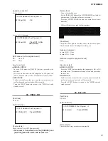
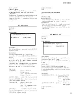
Turn on the power while holding down the [F1] and [SF6]
buttons simultaneously.
The opening screen will appear followed by the screen below.
Check the versions of the Firm, Kernel and Data.
Values at right in the screen indicate limit values of test items
07
̶
21, Trigger In test (see page 49). If you want to change
the limit values, select a parameter with the [
] and [
]
buttons and set a value with the rotary encoder. (The value
will be reset to the initial value when the power is turned off.)
Details of the parameters are shown below.
*
The range of all the parameters is 00 to 7f.
*
The “Min.” and “Max.” values show that the values
themselves are applicable as OK range.
ATT min:36 Lower limit of OK limit for signal levels
[
q
SNARE]
̶
[
!5
]
max:41
Upper limit of OK limit for signal levels
[
q
SNARE]
̶
[
!5
]
CR min:0c Lower limit of OK limit for time constant
values [
q
SNARE]
̶
[
!5
]
max:18
Upper limit of OK limit for time constant
values [
q
SNARE]
̶
[
!5
]
XT
:02
Upper limit of OK limit for crosstalk values
[
q
SNARE]
̶
[
!5
]
*
There is no need to change these values unless
otherwise specifi ed.
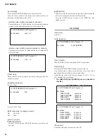
Press the [ENTER/STORE] to enter the “Test number
selection screen”.
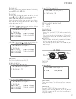
/ / / / DTXTREME III Test Program / / / /
Firm
Ver. :
*
.
**
Kernel Ver. :
*
.
**
~~~~~~~~~~~~~~~~
ATT min:36
<<
max:41
CR min:0c
max:18
XT :02
*
[ENTER] : Test Start
*
[F6]
: Factory Set
Data
Ver. :
*
.
**
*
[EXIT]
: Exit
*
.
**
:
Version number
/ / / / DTXTREME III Test Program / / / /
Firm
Ver. :
*
.
**
Kernel Ver. :
*
.
**
~~~~~~~~~~~~~~~~
ATT min:36
<<
max:41
CR min:0c
max:18
XT :02
Wating test code..
Data
Ver. :
*
.
**
*
[EXIT]
: Exit
*
.
**
:
Version number
Press the [F6] button to execute the Factory Set. (See “43.
Factory set” on page 61)
Press the [EXIT] button to
fi
nish the test mode followed by
normal operation mode. (See “44. Exit” on page 61)
MIDI MODE:
Turn on the power and wait for several seconds. After
checking that play screen is displayed, send
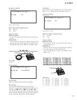
“F0 43 10 18
5A 00 F7”
and the following screen will be displayed.
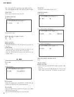
/ / / / DTXTREME III Test Program / / / /
01 : LCD,LED
: Press [ENTER]
The screen is “MIDI test code standby screen”.
Check the versions of the Firm, Kernel and Data.
Values at right in the screen indicate limit values of test items
07
̶
21, Trigger In test (see page 49) If you want to change the
limit values, send the following commands when the screen is
displayed.
F0 43 10 18 5B aa bb cc dd ee F7
aa=ATT_MIN,bb=ATT_MAX,cc=CR_MIN,dd=CR_MAX,ee=XT
(The value will be reset to the initial value when the power is
turned off.)
See the “
MANUAL MODE
” shown left for details of the
parameters.
*
There is no need to change the values unless other-
wise specifi ed.
Press the [EXIT] button to
fi
nish the test mode followed by
normal operation mode. (See “44. Exit” on page 61)
B. How to carry out tests
MANUAL MODE:
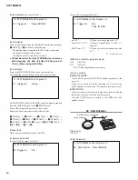
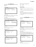
If you press the [ENTER/STORE] button when the test entry
screen is shown , the following screen will be displayed.
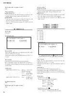
The screen is “Test number selection screen”. Select a test
number with the [DEC/NO] and [INC/YES] button and
press the [ENTER/STORE] button to execute the test for the
selected test number.
If a failure occurs, NG will be indicated and the test will be
aborted. (Some test items operate otherwise.)
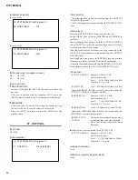
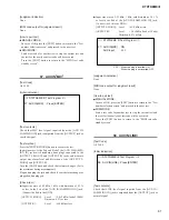
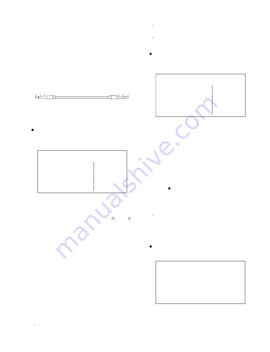
Standard stereo phone cable(TRS)
T
R
T
R
S
S
Summary of Contents for DTXTREME III
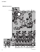
Page 30: ...DTXTREMEⅢ 30 B B DM Circuit Board 2NA WJ91030 2 ...
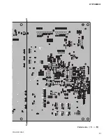
Page 31: ...31 DTXTREMEⅢ B B Pattern side パターン側 2NA WJ91030 2 ...
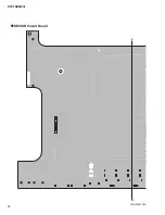
Page 34: ...DTXTREMEⅢ 34 D D DMSUB Circuit Board 2NA WJ91040 ...
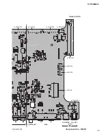
Page 35: ...35 DTXTREMEⅢ D D Pattern side パターン側 Scale 85 100 2NA WJ91040 ...
Page 38: ...DTXTREMEⅢ 38 F F JK Circuit Board 2NA WJ91050 2 ...
Page 39: ...39 DTXTREMEⅢ F F Pattern side パターン側 Scale 95 100 2NA WJ91050 2 ...
Page 42: ...DTXTREMEⅢ 42 H H or D PN Circuit Board 2NA WJ91060 2 ...
Page 43: ...43 DTXTREMEⅢ H H Pattern side パターン側 Scale 80 100 2NA WJ91060 2 ...

