19
DTXTREME
Ⅲ
4
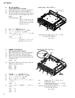
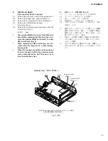
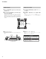
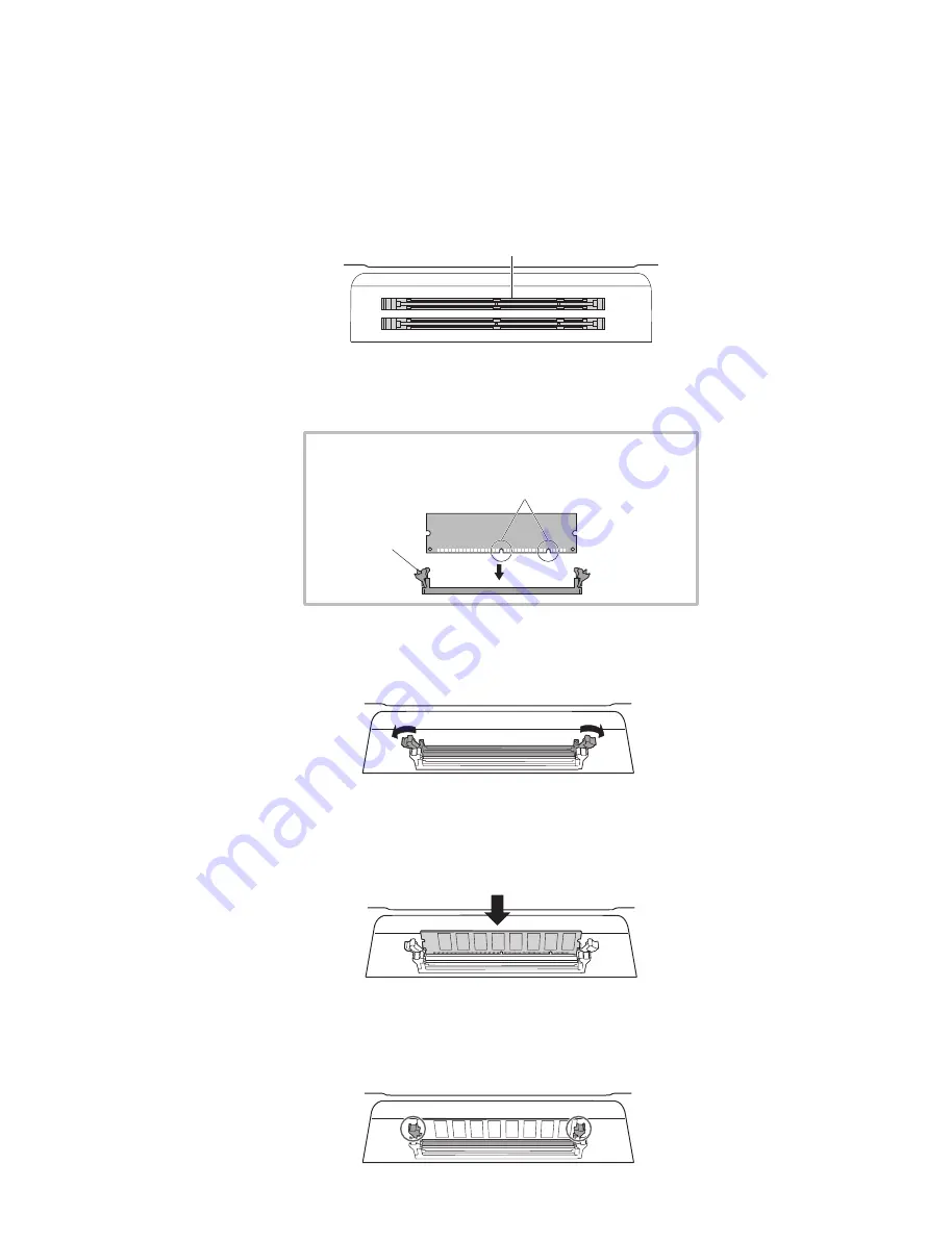
Insert the two DIMMs into the DIMM sockets.
DIMM slot
×
2
(DIMMスロット×2)
●
Location for DIMM installation
(DIMMの取り付け位置)
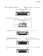
Installing the DIMM modules to the sockets
Make sure that the DIMM module is aligned correctly before you install it.
(DIMMの向きを確かめて取り付けてください。)
Ejector lever
(ロックレバー)
Notch for alignment
(切り欠き)
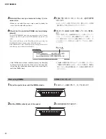
4-1 Press the ejector levers to the outside of the socket.
4-2 Insert the DIMM vertically in the socket.
Press the DIMM in fi rmly until it “snaps” or locks in
place.
Confirm whether or not both the levers are firmly
locked.
4
DIMM を 2 枚、DIMM スロットに垂直に奥まで差し
込みます。
DIMM スロットへの取り付け
4-1 左右のロックレバーを横に押して、倒します。
4-2 DIMM を垂直に、奥まで差し込みます。
同時にレバーが立ち上げられ、DIMM を固定した状態で
ロックされます。
ここで左右のレバーがしっかりロックされているか確認
してください。
Summary of Contents for DTXTREME III
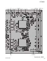
Page 30: ...DTXTREMEⅢ 30 B B DM Circuit Board 2NA WJ91030 2 ...
Page 31: ...31 DTXTREMEⅢ B B Pattern side パターン側 2NA WJ91030 2 ...
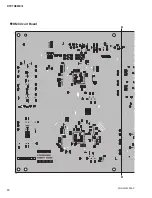
Page 34: ...DTXTREMEⅢ 34 D D DMSUB Circuit Board 2NA WJ91040 ...
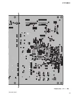
Page 35: ...35 DTXTREMEⅢ D D Pattern side パターン側 Scale 85 100 2NA WJ91040 ...
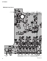
Page 38: ...DTXTREMEⅢ 38 F F JK Circuit Board 2NA WJ91050 2 ...
Page 39: ...39 DTXTREMEⅢ F F Pattern side パターン側 Scale 95 100 2NA WJ91050 2 ...
Page 42: ...DTXTREMEⅢ 42 H H or D PN Circuit Board 2NA WJ91060 2 ...
Page 43: ...43 DTXTREMEⅢ H H Pattern side パターン側 Scale 80 100 2NA WJ91060 2 ...

