DTXTREME
Ⅲ
10
DISASSEMBLY PROCEDURE
(分解手順)
1.
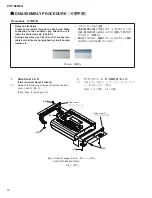
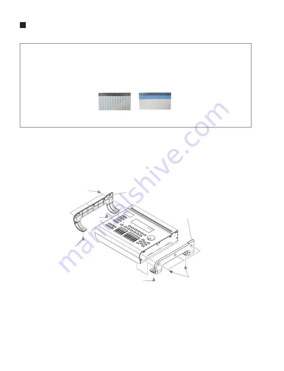
Side Cover L & R
(Time required: About 2 minute)
1-1
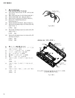
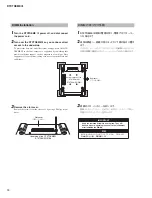
Remove the following screws and remove the side
cover L and R. (Fig. 1)
[400]: 5pcs. (L) and 5pcs. (R)
1.
サイドカバー L、R
(所要時間:約 2 分)
1-1
下記のネジを外して、サイドカバー L とサイドカ
バー R を外します。
(図 1)
[400]: 5 本(左側)
、5 本(右側)
[400]: PW Head Tapping Screw-B(B タイト+ PWH)
3.0X8 MFZN2B3 (WE975300)
Fig. 1 ( 図 1)
[400]
[400]
[400]
[400]
[400]
Side cover L
(サイドカバー L)
Side cover R
(サイドカバーR)
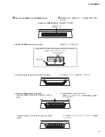
Notes on Flat Cable
Contacts are visible through the back side. When
connecting to the connector, pay attention not to
insert the cable inversely. (Photo A)
During assembly, pay attention that connectors,
cables or the like are not pinched by circuit boards,
frames, etc.
•
•
フラットケーブルの注意
接点が裏面から透けて見えます。コネクタにケーブル
の表・裏を逆に差し込まないように注意して取り付け
てください。
(写真 A)
組み立てるときは、基板やフレームなどでコード類を
はさまないように注意してください。
•
•
Precautions
(注意事項)
Photo A ( 写真 A)
Summary of Contents for DTXTREME III
Page 30: ...DTXTREMEⅢ 30 B B DM Circuit Board 2NA WJ91030 2 ...
Page 31: ...31 DTXTREMEⅢ B B Pattern side パターン側 2NA WJ91030 2 ...
Page 34: ...DTXTREMEⅢ 34 D D DMSUB Circuit Board 2NA WJ91040 ...
Page 35: ...35 DTXTREMEⅢ D D Pattern side パターン側 Scale 85 100 2NA WJ91040 ...
Page 38: ...DTXTREMEⅢ 38 F F JK Circuit Board 2NA WJ91050 2 ...
Page 39: ...39 DTXTREMEⅢ F F Pattern side パターン側 Scale 95 100 2NA WJ91050 2 ...
Page 42: ...DTXTREMEⅢ 42 H H or D PN Circuit Board 2NA WJ91060 2 ...
Page 43: ...43 DTXTREMEⅢ H H Pattern side パターン側 Scale 80 100 2NA WJ91060 2 ...


