–17–
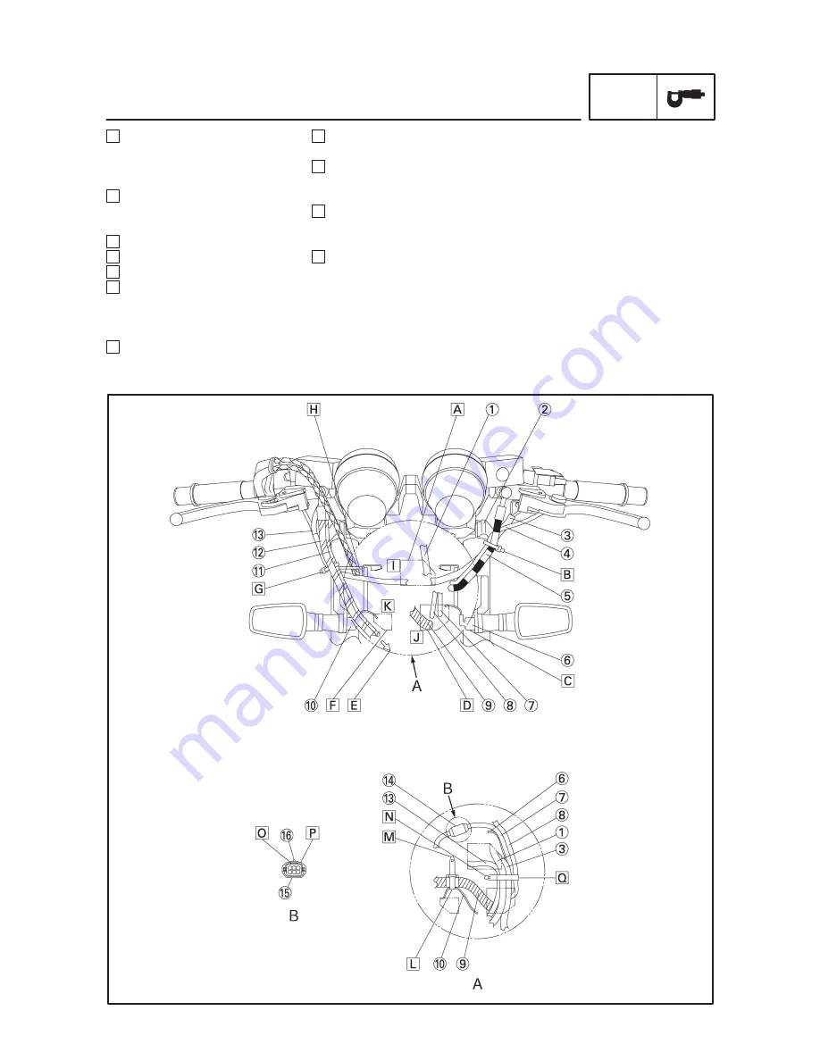
N Tighten the clamp pointing the
tip to the inward.
O Install the coupler locking sec-
tion facing the housing connec-
tor 2.
P Place the cover onto the coupler
for the immobilizer lead and wire
harness.
Q Clamp the main switch lead, im-
mobilizer lead, left handlebar
switch lead, right handlebar
switch lead, front turn signal light
(left) and meter lead.
SPEC
CABLE ROUTING
G Bind the right handlebar switch
lead and brake hose 2 by the
side of the wire guide of the
headlight stay with a clamp.
H Pass the throttle cables through
the wire guide of the headlight
stay.
I To the upper hole
J To the left side of the lower hole
K To the right side of the lower hole
L Clamp the right front turn signal
light lead and wire harness.
Clamp the wire harness aligning
with the positioning tape.
M Tighten the clamp pointing the
tip to the upward.


