background image

Instruction #1035998F - Page 10 of 14

ABRAZADERAS PARA BARRAS 

LOCKNLOAD (RACK DE TECHO)

ABRAZADERAS PARA BARRAS LOCKNLOAD (HD PARA CAMIONETAS)

OTROS USOS

• GUÍA DE COMPATIBILIDAD DE LA PLATAFORMA •


•  Separación mínima entre barras transversales: 27.5” (700 mm).
•  Los bloques de montaje se deben asegurar al segundo travesaño al 

menos, a partir de los extremos. NOTA: Respete esta recomendación 
cuando instale una plataforma que incluya 3 pares de bloques de 
montaje en un portaequipaje para techo de dos barras. En ese caso, 
el par de bloques de montaje centrales no se debe utilizar.

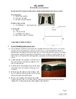
•  No instale la plataforma con el reborde del riel encima de los bloques 

de montaje, como se ilustra a la derecha.

•  Centre la plataforma cuando sea posible.
•  La plataforma se puede deslizar hacia adelante sobre los bloques de 

montaje con el fin de ganar más espacio para la portezuela trasera.

•  Para un sistema de 3 o más barras transversales, separe las del 

centro de manera que la distribución del peso resulte uniforme.

•  Asegúrese de que las abrazaderas se 

encuentren lo más espaciadas posible, pero 

DENTRO del espacio entre las torres.

RECOMENDACIONES PARA USOS ESPECÍFICOS

Plataforma H

Plataforma B

Plataforma E

Plataforma J

Plataforma K 

Plataforma N

RECOMENDACIONES PARA USOS GENERAL

TORRES TIMBERLINE O SKYLINE 

(RIELES LATERALES O GUÍAS 

AJUSTABLES)

•  Ajuste las torres delanteras para que 

queden lo más alejadas posible.

•  Consulte las instrucciones de las torres 

TimberLine o patines Landing Pad para 

realizar el ajuste.

TORRES SKYLINE (POSICIÓN FIJA)

•  Coloque una toalla sobre el 

techo antes de instalar los 

bloques de montaje armados.

•  Asegúrese de que las abrazaderas para las barras transversales LockNLoad queden lo más 

separadas posible sobre dichas barras. Es preferible que queden al exterior de las torres.

•  Consulte las medidas de más 

arriba para el caso de otros usos.

ANCHO

X

Y

ESPAÑOL

Plataforma

Ancho

Largo

X

Y

K

49” 

1245 mm

55” 

1397 mm

26” - 37.25”

660 mm - 946 mm

27” - 33”

686 mm - 838 mm

B

54”

1372 mm

60”

1524 mm

31.5” - 42.5”

800 mm - 1080 mm

27” - 39”

686 mm - 991 mm

J

65”

1651 mm

76”

1930 mm

42.5” - 53.5”

1080 mm - 1959 mm

28” - 54.5”

711 mm - 1384 mm

E

49”

1245 mm

84”

2134 mm

26” - 37.25”

600 mm - 946 mm

35” - 62.5”

889 mm - 1588 mm

N

54”

1372 mm

84”

2134 mm

31.5” - 42.5”

800 mm - 946 mm

35” - 62.5”

889 mm - 1588 mm

H

62”

1575 mm

84”

2134 mm

39” - 50.5”

991 mm - 1283 mm

35” - 62.5”

889 mm - 1588 mm

Min. - Max.

Min. - Max.

Summary of Contents for LockNLoad Platform

Page 1: ...2 x2 x2 x2 x2 x2 2 Platform Corner x4 x4 x4 x4 x4 x4 3 Slat x6 x7 x9 x10 x10 x10 4 M6 T Nut x8 x8 x8 x8 x8 x8 5 M6 Capscrew 25 mm with Washer x10 x10 x10 x10 x10 x10 6 M6 Capscrew 16 mm with Washer x3...

Page 2: ...sible but INBOARD of towers SPECIFIC APPLICATION GUIDELINES Platform B Platform K Platform J Platform E Platform N Platform H GENERAL TIMBERLINE TOWERS OR SKYLINE TOWERS SIDE RAILS OR ADJUSTABLE TRACK...

Page 3: ...E PLATFORM ENDS AND SIDES Install the Platform end assemblies created in Step 2 to the Platform sides Push firmly until fully inserted INSTALL CORNER BRACES Install the corner braces to the corner pie...

Page 4: ...rking outwards secure each slat end using two M6 x 16 mm capscrews with washers as shown Tighten all screws to 4 Nm with a 4 mm hex wrench or torque wrench 4 Nm A B Carefully flip the Platform over an...

Page 5: ...ts as shown C Being sure the M8 T bolt is captured in the slot beneath the platform support use a 13 mm wrench to fully tighten the nuts to 7 Nm Then use a hex or torque wrench to tighten the capscrew...

Page 6: ...rt one M8 T bolt into each channel of the mounting blocks on either side of the slats Twist the T bolts so that they are captured by the channels B Lower the slat clamp onto the T bolt and install an...

Page 7: ...ross the length of the deflector Installation is the reverse and should be confirmed by hearing an audible CLICK when the deflector is fully installed OPTIONAL WIND DEFLECTOR REMOVAL TIMBERLINE TOWERS...

Page 8: ...0 x10 x10 4 Plaquette filet e M6 x8 x8 x8 x8 x8 x8 5 Vis t te bomb e M6 x 25 mm avec rondelle x10 x10 x10 x10 x10 x10 6 Vis t te bomb e M6 x 16 mm avec rondelle x32 x36 x48 x52 x52 x52 7 Renforts de p...

Page 9: ...ient le plus espac es possible mais L INT RIEUR des pieds CONSIGNES SP CIFIQUES Plateforme H Plateforme B Plateforme E Plateforme J Plateforme K Plateforme N G N RALIT S PIEDS TIMBERLINE OU SKYLINE LO...

Page 10: ...DENTRO del espacio entre las torres RECOMENDACIONES PARA USOS ESPEC FICOS Plataforma H Plataforma B Plataforma E Plataforma J Plataforma K Plataforma N RECOMENDACIONES PARA USOS GENERAL TORRES TIMBER...

Page 11: ...s los tornillos con una fuerza de 4 Nm CONSEJO Presione con firmeza e incline los tornillos M6 x 20 mm hacia la abertura de los orificios A Glisser chaque latte en position sous le rebord des profil s...

Page 12: ...evrait entendre un clic tr s net quand il est bien engag NOTA Es posible desmontar el deflector para poder adaptar ciertos anclajes accesorios a instalar en la extrusi n delantera Para esto simplement...

Page 13: ...ours de trajet et provoquer un grave accident C est pourquoi la pose la manutention et l utilisation de ce produit doivent tre conformes aux instructions visant le produit et le v hicule En plus d obs...

Page 14: ...o Carga m xima del techo peso del portaequipaje para techo peso de los accesorios de transporte peso de la carga La carga debe estar uniformemente distribuida con el centro de gravedad lo m s bajo pos...

Reviews: