background image

42

  When the internal GPS unit is not activated or can-

not receive a fix even it is activated,  the upside of 

the compass rose always indicates the direction 

of the runway and no sign indicating the bearings 

is displayed on the compass rose.

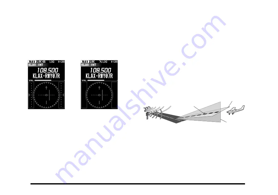
 When the internal GPS unit is activated and re-

ceives a fix, the compass rose rotates to display 

the approaching course up.

108.500

N 3

33

15

21

6

30

12

24

E

W

S

108.500

Without GPS

With GPS, no GS signal

Note: 

You may change the COM band receive frequency 

while receiving an ILS signal. If the [

ENT

] key is 

pressed while the tag name of the airport is selected, 

the recall screen listing the frequencies you have used 

will temporarily appear on the display, so that you may 

select a frequency from the list with the [

] or 

] key 

or change the frequency with the DIAL knob.

Terminology: 

 The localizer signal guides the approach to the 

runway in horizontal direction.

  The glide slope signal guides the approach to the 

runway in vertical direction. Note that some airports 

are unequipped with the glide slope.

Runway

Course of approach

Guided by 

glide slope

Glide slope

Localizer

Guided by 

localizer

Summary of Contents for FTA-850L

Page 1: ...Operating Manual AIR BAND TRANSCEIVER FTA 850L ...

Page 2: ...t the connected Bluetooth headset 34 Connect to another paired Bluetooth headset 35 VOX Operation 37 Reception of VOR Signals 38 Reception of ILS Signals 41 Split Operation 43 Reception of Weather Channel Broadcasts 45 Dual Watch Operation 46 TOT Feature 47 Saving the Battery during Reception 47 Using the Headset Microphone 48 Side Tone Control 48 Changing the Channel Steps 49 ANL Feature 49 Compa...

Page 3: ... be easily reprogrammed in minutes using the optional PC Programming Software and your PC and additionally provide positioning and navigation features realized by the internal GPS unit We recommend that you read this manual in its entirety so as to understand the many features of the FTA 850L completely Keep this manual handy so you may use it for reference Note The VOR ILS and GPS navigation feat...

Page 4: ...lection or entered values On the DD Dual frequency Display screen use this key to switch the display mode FUNC Key Press this key to display the Function menu screen MENU Key Press this key to display the MENU screen Press and hold this key to dis play the SETUP menu screen SAVE Key Press and hold this key to store the current channel information to the memory BACK Key LOCK Key Press this key to r...

Page 5: ...nob Transmitting Press the PTT switch Recall the previously used frequency COMM Mode Press the key to select the frequency Press the ENT key Registering Channels to Memory Registering Memories Tune to the frequency Press and hold the SAVE key Press the SAVE key Recalling Memories Press the MENU key Press the key or rotate the DIAL knob to select MEMORY Press the ENT key Press the key or rotate the...

Page 6: ...IAL knob to select the Mode Press the MENU key Press the ENT key To return to the previous screen press the BACK key during the operation In SETUP on the MENU screen you can make various settings for the radio and settings related to communication See page 75 for details ...

Page 7: ...is displayed during reception and the icon is displayed during transmission Press the ENT key Press the MENU key to select the desired screen and then press the ENT key Pressing the BACK key does not return to the previous screen To change the screen MEMORY CH Mode Page 51 Press the MENU key Select MEMORY Press the ENT key MEMORY CH mode cannot be called if nothing is stored in memory The name tag...

Page 8: ...de Press the MENU key to select the desired screen and then press the ENT key Pressing the BACK key does not return to the previous screen To change the screen GPS Compass Screen Page 50 Press the MENU key Select COMPASS Press the ENT key N 3 33 1 5 2 1 6 3 0 1 2 2 4 E W S Compass rose Course indicator COG course over ground value SOG speed over ground value Altitude value Date obtained from the G...

Page 9: ... key Press the COMM key to return to COMM mode Press the MENU key to select the desired screen and then press the ENT key Press the BACK key to return to the previous screen To change the screen Timer Screen Page 69 Press the MENU key Select TIMER Press the ENT key Stop watch Countdown timer Press the ENT key Press the COMM key to return to COMM mode Press the MENU key to select the desired screen...

Page 10: ...U key Select DD Press the ENT key The grayed out display cannot be operated Transmit and receive operations may be performed on the screen displayed in white characters Press the ENT key Switch screens by pressing the keys Press the COMM key to return to COMM mode Press the MENU key to select the desired screen and then press the ENT key Pressing the BACK key does not return to the previous screen...

Page 11: ...MM key does not return to COMM mode Press the MENU key to select the desired screen and press the ENT key Pressing the BACK key does not return to the previous screen To change the screen ILS CDI Screen Page 41 N 3 33 1 5 2 1 6 3 0 1 2 2 4 E W S 108 500 Compass rose Course runway indicator Deviation marks for localizer Height deviation indicator for glide slope Deviation marks for glide slope Cour...

Page 12: ...ss the PTT switch to transmit at the split frequency set in the COMM Setup menu Page 43 The location information of this station as received from the built in GPS is saved in the internal memory at regular intervals Page 74 Press the BACK key to return to the previous screen Select a destination or route and start a new navigation Page 64 Display the route display screen during route navigation Pa...

Page 13: ...pproved for use by the general population in an uncontrolled environment This radio is restricted to occupational use work related operations only where the radio operator must have the knowledge to control its RF exposure conditions When transmitting hold the radio in a vertical position with its microphone 1 to 2 inches 2 5 to 5 cm away from your mouth and keep the antenna at least 1 inch 2 5 cm...

Page 14: ...hone SEP 10A 2 2 available only with the SSM 20A Earphone SEP 11A Quick Release Holster SHB 110 Belt Clip Hanger SCH 11 PC Programming Software YCE46 Download the YCE46 PC Programming Software from the YAESU website Availability of accessories may vary Some accesso ries are supplied as standard per local requirements while others may be unavailable in some regions Consult your YAESU Dealer for det...

Page 15: ...u are operating in the COM band Release this button to return to the Receive mode See page 25 for details SQL Squelch Switch Adjust the squelch level by pressing this button and then turning the DIAL knob Press and hold this button to open the squelch continuously Press this button again to resume normal quiet monitoring See page 24 for details Microphone Speak into this opening in a normal voice ...

Page 16: ... memory mode and WEATHER CH Press on the COMPASS NAVI TIMER VOR ILS Location INFO or GPS INFO screen to display the previously used frequency history selection screen or the memory channel WX channel selection screen FUNC Key PressthiskeytodisplaytheFunctionmenuscreen MENU Key Press this key to display the MENU screen Press and hold this key to display the SETUP menu screen SAVE Key Press and hold...

Page 17: ...s removed DATA Jack You may connect the optional USB cable to this jack To use this jack you must first lift the rubber cover away from the transceiver body Do not allow the FTA 850L to get wet while the rubber cover is removed EXT DC Jack When an external 9 5 to 10 5 Volt DC power source is available you may connect the SDD 12 Cigarette Lighter DC DC Converter here 1 Do not allow the FTA 850L to ...

Page 18: ...f slide the locking plate until the UNLOCK appears entirely lift up the end of the battery pack by press ing the battery pack latch then pull out the battery from the radio Do not attempt to open any of the re chargeable Lithium ion packs as per sonal injury or damage to the Lithium ion pack could occur if a cell or cells become acciden tally short circuited Batteries and Chargers The SBR 39LI is ...

Page 19: ...he heat of fire may cause bat tery cells to explode and or release dangerous gases z z Battery Maintenance Forsafeandproperbatteryuse pleaseobservethefollowing Battery packs should be charged only in non hazardous environments Do not attempt charge a pack with the incorrect charger as this can damage or shorten the life of the pack Keep the battery contacts clean z z Battery Storage When a battery...

Page 20: ...When installing a cell insert the end first then press in the end so the cell snaps into place Pay attention to the polarity indicated inside the case SBT 12 Alkaline Battery Tray Battery Charging If the radio has never been used or its charge is de pleted it may be charged by connecting the SBH 11 Charger Cradle with the SAD 25 AC Adaptor 1 Install the Lithium ion battery pack onto the trans ceiv...

Page 21: ...TA 850L under the conditions below Battery saver ON Operation ratio TX RX Standby 6 6 48 sec External DC Power Supply Connection You may insert the cable plug of the optional SDD 12 Cigarette Lighter DC DC Converter into the EXT DC jack located on the right side of the transceiver In this case the icon will appear in the top right corner of the LCD display When making DC connections via the SDD 12...

Page 22: ...a to the FTA 850L grasp the base of the antenna firmly and exert a moderate pinching pressure on the base as you press the antenna onto the radio s antenna connector While exerting this pressure rotate the antenna clockwise 1 4 turn to lock the antenna in place Belt Clip Installation You may mount the clip to the rear of the FTA 850L using the supplied screws ...

Page 23: ...crews attached to the SCU 42 Either of the plug directions are acceptable as long as the both screws fit the screw holes 4 Insert the plugs of the headset to the sockets of the SCU 42 Precautions The FTA 850L are capable of two way communi cation on channels used for critical aviation safety communications Therefore it is important that this radio be kept away from children or other unauthor ized ...

Page 24: ...ll be dis played If you agree with the warn ing message press the ENT key A channel frequency will appear on the display If not press the COMM key The icon appears on the display when the audio signal is received on the current frequency To turn the radio off press and hold the POWER switch Basic Operation ...

Page 25: ...3 4 3 5 To set 118 275 MHz you do not need to press the final 5 in the frequency as below press 1 1 8 2 7 You may recall the operat ing frequency that you have used by pressing the or key then press the ENT key The frequencies used in the past are listed in order on the display Adjusting the volume Rotate the VOL inner knob to set the volume level If no signal is present press and hold the SQL swi...

Page 26: ...the SQL switch The squelch will remain open and you should have a better chance of hearing weak signals To return to normal operation press the SQL switch momentarily Accessing the 121 5 MHz Emergency Frequency The FTA 850L can quickly access the 121 500 MHz emergency frequency This function can be activated even when the keypad lock function described on page 28 is in use To access the emergency ...

Page 27: ...n of the microphone s location so as to ensure sufficient voice input to the radio Refer to the illustra tion and observe the location of the internal microphone If you find it difficult to utilize the FTA 850L conve niently and safely while speaking directly into the microphone we recommend the use of the SSM 20A Speaker Microphone option the SSM BT10 Blue tooth Headset option or an aftermarket a...

Page 28: ... the MENU screen displayed by pressing the MENU key on the front panel When turning on the FTA 850L the last mode you have used before turning off will automatically be entered COMM mode The basic operating mode for communication Navigation through the NAV band is also per formed on this mode DD Dual Freqency Display mode In this mode two channels are displayed at the top and bottom of the screen ...

Page 29: ...nditions You can also switch to the SETUP menu screen by press and hold the MENU key Function Menus TheFTA 850Lhasthreefunction menus Pressing the FUNC key displaysamenuoffrequentlyused functions in the current mode You can access the functions just by pressing a number on the numeric keypad of the desired function listed on the display You can also select a function with the keys or the DIAL knob...

Page 30: ... to the Config menu z z Activating the lock feature Press and hold the BACK key According to the setting of the lockout configura tion either of Key Lock DIAL Lock or All Lock will appear on the screen for 2 seconds and then the display will return to the previous screen While the FTA 850L are locked the controls with the VOL inner knob and or the keys except the PTT switch the POWER switch the SQ...

Page 31: ...ressing the or key and then press the ENT key 3 Select Reset on the screen by pressing the or key and then press the ENT key 4 Select Factory on the screen by pressing the or key and then press the ENT key 5 Select OK on the screen by pressing the or key and then press the ENT key The initialization will start and then Complete will be displayed after the radio returns to factory default ...

Page 32: ...ed in white letters The Inactive Channel Displayed in gray letters 1 Press the MENU key to display the MENU screen 2 Select DD on the screen by pressing the or key and then press the ENT key The DD Dual Frequency Display screen is shown The mode used before switching to DD mode becomes the active channel in DD mode The display that was previously active in DD mode becomes the active channel Notes ...

Page 33: ...the active channel Pressthe keytomakethelowerchanneltheactivechannel z z Selecting the mode Each time you press the ENT key the active channel mode switches as follows COMM MEMORY WEATHER CH Advice As shown in the display example below you can select the mode individually for the upper and lower channels of the screen z z Changing the memory group MEMORY mode only Each time you press and hold the ...

Page 34: ...ooth Headset and the FTA 850L must be paired This step is only necessary when first connecting the headset 1 To start the Bluetooth headset in pairing mode SSM BT10 Press and hold the Multi Function Button until the SSM BT10 LED blinks red blue alternately 2 Press and hold the MENU key to display the SETUP menu screen Power ON Blinks red and blue Press and hold the Multi Function Button to turn ON...

Page 35: ...d press the ENT key 9 Press the BACK key several times to return to normal operation While connected to a Bluetooth headset the icon lights up on the FTA 850L screen and the received audio and operation beep will be heard from the Bluetooth headset z z Bluetooth headset volume control Adjust the volume of the Bluetooth headset with either the VOL knob on the FTA 850L or the vol ume control operati...

Page 36: ...e Call button again to return the FTA 850L to receive The button name may differ depending on your Bluetooth headset SSM BT10 When the Multi Function Key is pressed a beep will sound and the FTA 850L will continuously transmit Press briefly to transmit Press the Multi Function Key again a beep will sound and the FTA 850L will return to receive mode Hands free VOX operation with a Bluetooth headset...

Page 37: ...th Headset Connect to another paired Bluetooth headset 1 Select the Bluetooth de vice to be connected in step 4 above and press the ENT key 2 Press the ENT key The connection will start W h e n p a i r i n g i s complete Connected is displayed z z Remove a registered paired Bluetooth device from the list 1 Select the Bluetooth device to be deleted in step 4 above and press the ENT key 2 Select Del...

Page 38: ...ional SSM BT10 does not support this function 1 Press and hold the MENU key to display the SETUP menu screen 2 Select Bluetooth on the screen by pressing the or key and then press the ENT key 3 Select Mic Sense on the screen by pressing the or key and then press the ENT key 4 Select ON on the screen by pressing the or key and then press the ENT key ...

Page 39: ...ctivate the VOX system select ON on the item VOX of the COMM Setup menu in the SETUP mode The icon which indicates that the VOX system is active will appear at the right side of the channel frequency when the display returns to the COM band screen To adjust the VOX gain select one of the follow ing gain levels on the item VOX Level of the COMM Setup menu in the SETUP mode MIN Level1 Level2 Level3 ...

Page 40: ...to 0 degree when you use the FTA 850L for the first time The last value you have set as the OBS will be displayed next time the VOR screen appears The upside of the compass rose always indicates the direction set as the OBS When the OBS is set to a degree within the TO range relative to the VOR signal the FTA 850L displays a degree adding or subtracting 180 to or from the VOR signal as the VOR val...

Page 41: ...310 320 330 340 350 300 230 VOR Station Magnetic North N OBS 50 VOR 230 N 3 3 3 1 5 2 1 6 3 0 1 2 2 4 E W S If the OBS is set to 50 but your aircraft is at 236 from a certain VOR station for example you are off course and the course deviation needle of the CDI will be inside the right half of the compass rose 10 0 20 30 40 50 60 70 80 90 100 110 120 130 140 150 160 170 180 190 200 210 220 230 240 ...

Page 42: ... Func menu screen 3 Press the ENT key or the 1 key The OBS omni bearing selector on the screen is selected N 3 33 1 5 2 1 6 3 0 1 2 2 4 E W S 4 Enter the course to the VOR station with the keypad or the DIAL knob 5 Press the ENT key again to return to the previous screen N 3 3 3 15 21 6 3 0 1 2 2 4 E W S 6 Correct your course until the course deviation needle on the screen is at the cen ter of the...

Page 43: ... 1 6 3 0 1 2 2 4 E W S Reception of ILS Signals When the FTA 850L receive an ILS instrument landing system signal the display will automatically switch to the NAV band screen which shows a CDI course deviation indicator based on the received signal and LOC and or GS which indicates that the FTA 850L are receiving the localizer signal and or glide slope signal N 3 33 1 5 2 1 6 3 0 1 2 2 4 E W S 108...

Page 44: ...hange the COM band receive frequency while receiving an ILS signal If the ENT key is pressed while the tag name of the airport is selected the recall screen listing the frequencies you have used will temporarily appear on the display so that you may select a frequency from the list with the or key or change the frequency with the DIAL knob Terminology The localizer signal guides the approach to th...

Page 45: ... 3 33 1 5 2 1 6 3 0 1 2 2 4 E W S On course CDI Examples Corresponding to Aircraft Location Runway is to be at the back of the screen Split Operation The split operation feature allows you to transmit a call to a flight service station using the COM band frequencies while receiving a station in the NAV band VOR stations equipped with this capability typically are shown on navigation charts with th...

Page 46: ...n by pressing the or key and then press the ENT key The same operation as above is possible by press ing the 3 key If ON is displayed in the right hand of Split the FTA 850L are already in the split mode The display will return to the previous screen and the icon which indicates that the FTA 850L are in the split mode will appear on the display z z Operating in the split mode To transmit a voice c...

Page 47: ...el frequency selec tion press the ENT key To exit the WX mode press the MENU key select the mode other than WEATHER on the screen by pressing the or key and then press the ENT key z z Weather alert reception In the event of extreme weather disturbances such as storms and hurricanes the NOAA National Oceanic and Atmospheric Administration sends a weather alert accompanied by a 1050 Hz tone and subs...

Page 48: ...MM Setup on the screen by pressing the or key and then press the ENT key 3 Select Dual Watch Freq on the screen by pressing the or key and then press the ENT key 4 Enter the frequency you want to poll with the key pad 5 Select FINISH on the screen by pressing the or key and then press the ENT key The frequency will be deter mined and the display will return to the COMM Setup menu z z Starting the ...

Page 49: ... the transceiver after continuous transmission exceeds the programmed time This feature prevents unintended transmission by mistake and reduces battery consumption To select the TOT select either of 1min 2min 3min 4min 5min on the item TX TOT of the COMM Setup menu in the SETUP mode Saving the Battery during Reception One of the important features of the FTA 850L are its battery saver which puts t...

Page 50: ... to use the PTT switch of the radio we recommend to use an aftermarket external PTT switch See page 89 for details Side Tone Control When utilizing an external headset you may monitor your own voice talking to the microphone through the headphone Note Do not activate the side tone function when connect ing the optional microphone SSM 20A To activate the monitoring of your voice side tone select on...

Page 51: ...trol etc will call out the frequency according to what the display indicates Operating Frequency Display 8 33 kHz Step 25 kHz Step 1xx 0000 MHz 1xx 005 1xx 000 1xx 0083 MHz 1xx 010 1xx 0166 MHz 1xx 015 1xx 0250 MHz 1xx 030 1xx 025 1xx 0333 MHz 1xx 035 1xx 0416 MHz 1xx 040 1xx 0500 MHz 1xx 055 1xx 050 1xx 0583 MHz 1xx 060 1xx 0666 MHz 1xx 065 1xx 0750 MHz 1xx 080 1xx 075 1xx 0833 MHz 1xx 085 1xx 09...

Page 52: ... while displaying the position information PTT Lock Function This function prevents accidental transmissions by locking or disabling the PTT switch You may selects enable or disable the PTT lock function for internal PTT external PTT or both 1 Press and hold the MENU key to display the SETUP menu screen 2 Select Config on the screen by pressing the or key and then press the ENT key 3 Select PTT Lo...

Page 53: ...n by pressing the or key and then press the ENT key The last recalled group will be displayed on the screen 3 Press and hold the ENT key to select the desired memory group All GROUP1 GROUP9 All Note Groups that have not been stored are not displayed The memory channels belong to either of the fol lowing groups All Group including all the memory channels GROUP1 to GROUP9 Groups of memory channels t...

Page 54: ... key to select the item then press the ENT key 2 Input letters and or numerics with the keypad or the DIAL knob or select a setting with the or key then press the ENT key 3 After all the inputs or changes have been done press the SAVE key or select SAVE at the bottom of the display with the or key then press the ENT key to store them into the memory Press the BACK key to cancel the changes or in p...

Page 55: ...f Name channel tag You must input either of Freq channel frequen cy or Lat and Lon position information of the channel z z Editing the information 1 Press and hold the MENU key to display the SETUP menu screen 2 Select Memory Book on the screen by pressing the or key and then press the ENT key 3 Select Edit by pressing the or key and then press the ENT key 4 Press the or key to select the group in...

Page 56: ... OK on the screen by pressing the or key and then press the ENT key The display will return to the previous screen after the deletion of the entry from the memory z z Setting the group name 1 Press and hold the MENU key to display the SETUP menu screen 2 Select Memory Book on the screen by pressing the or key and then press the ENT key 3 Select Group Name by pressing the or key and then press the ...

Page 57: ...uency according to the direction of the DIAL knob rotation When the scanner encounters a signal the scan ning pauses and the frequency indication on the display blinks and the radio remains on that chan nel until the signal disappears If the transceiver is turned OFF while scanning when the transceiver is turned ON scanning will resume To stop the scanning press the PTT switch or select SCAN again...

Page 58: ... the ENT key 4 Select the desired scan op eration by pressing the or key and then press the ENT key ALL Band 108 137 MHz COMMBand 118 137MHz NAVI Band 108 118 MHz The setting will be determined and the display will return to the COMM Setup menu Scanning the Memory Channels Among the memory you may scan only those on which you want to see if a signal exists z z Marking the channels 1 Press and hold...

Page 59: ... then perform steps 2 to 4 of the section Marking the channels in the page 56 1 Set the radio to the MEMORY mode 2 Press the FUNC key to display the COMM Func menu screen 3 Select Scan on the screen by pressing the or key and then press the ENT key The same operation as above is possible by press ing the 2 key The scanning starts and the display returns to the MEMORY mode screen Note When you enab...

Page 60: ...tured to obtain your position Starting Navigation 1 Press the MENU key to display the MENU screen 2 Select NAVI on the screen by pressing the or key and then press the ENT key The screen for selecting the destination is displayed Select the destination or the route There are three ways to select a destination or route Select a destination or route from memory Select the stored memory including lat...

Page 61: ...hen a route is selected The route confirmation screen is displayed Waypoints reg istered in route order are displayed from bottom to top Destination Waypoint Orign Display the latitude and longitude of waypoints on the route confirmation screen If you select a route press the keys to select a waypoint and press the ENT key to display the latitude and longitude of that point Press the ENT key or th...

Page 62: ...he flip flop in COMM mode or the memory list in memory mode will be displayed temporarily while the navigation continues Flip flops or memory channels may be selected by pressing the keys About 15 seconds after pressing the BACK key or stopping the operation the navigation screen will be returned Notes Waypoints and destination distances can be set in the GPS Setup Arrival Range see page 83 When R...

Page 63: ...em and press the ENT key 3 Press the keypad or select a number or letter with the DIAL knob and press the ENT key 4 Repeat step 3 and enter all the location information To correct a typo press the or key to move the cursor to the digit to change and then repeat step 3 5 Press the keys to select FINISH and press the ENT key The entered information is displayed 6 Press the keys to select GOTO and pr...

Page 64: ...on you are currently flying and the next waypoint 1 Press the FUNC key to display the NAVI Func screen 2 Press the keys to select Continue and press the ENT key The same operation as above is possible by press ing the 2 key Route display screen Destination Waypoint Next Waypoint Current position Origin When arriving at a waypoint the screen refreshes to show the section you are currently position ...

Page 65: ...rted and you will be able to return to the waypoints you have passed from the starting point Origin in the reverse order 1 Press the FUNC key to display the NAVI Func screen 2 Press the keys to select Back and press the ENT key The same operation as above is possible by press ing the 4 key 3 A confirmation screen will be displayed To return to the starting point press the ENT key Navigation to the...

Page 66: ...ute page 58 A new navigation will start Save the route in memory You can register up to 40 routes by registering memory channels that store latitude and longitude information as destinations departure points and waypoints 1 Press and hold the MENU key to display the SETUP menu screen 2 Select Memory Book on the screen by pressing the or key and then press the ENT key 3 Press the keys to select New...

Page 67: ...splayed Only the memory where the latitude longitude information is stored is displayed 8 The set destination e g KLAX APP is displayed Add waypoints 9 To add a waypoint se lect the waypoint one line above in the order you want to add and press the ENT key If you do not want to add a stop proceed to Set the departure point step 13 Note Waypoints cannot be added if the departure point is selected 1...

Page 68: ...teps 6 and 7 The set departure point will be displayed e g PASO ROBLES 16 Press the keys to select SAVE and press the ENT key to save the route in memory This completes saving the route z z Change overwrite waypoints You can change the waypoints you registered while editing the route 1 Press the keys to select the waypoint you want to change and then press the ENT key 2 Press the keys to select Ov...

Page 69: ...Delete and then press the ENT key Waypoints will be deleted Edit the stored route You can edit the stored route in Memory Book in the setup menu 1 Press and hold the MENU key to display the SETUP menu screen 2 Select Memory Book on the screen by pressing the or key and then press the ENT key 3 Press the keys to select New and then press the ENT key 4 Press the keys to select the memory group in wh...

Page 70: ...mory Book on the screen by pressing the or key and then press the ENT key 3 Press the keys to select Delete and then press the ENT key 4 Press the keys to select the memory group in which the route you want to delete is saved and press the ENT key 5 Press the or key to select the route you want to delete and then press the ENT key 6 The confirmation screen will be displayed To delete press the or ...

Page 71: ...y and then press the ENT key 3 Select STOPWATCH on the screen by pressing the or key and then press the ENT key 4 To start the counting select START on the screen by pressing the or key and then press the ENT key The displayed time will increase and START changes to STOP The icon appears on the top right of the display while counting 5 To stop the counting se lect STOP and press the ENT key To res...

Page 72: ...r screen Using the countdown timer 1 Press the MENU key to display the MENU screen 2 Select TIMER on the screen by pressing the or key and then press the ENT key 3 Press the ENT key 4 Press the or key to move the cursor to hour minute or second 5 Input the time with the key pad or the DIAL knob and then press the ENT key Press the BACK key to cancel the input time 6 To start the counting select ST...

Page 73: ...equencies you have used temporarily on the display so that you may select a frequency from the list with the or key or change the frequency with the DIAL knob Press the BACK key again to return to the Timer screen When the countdown timer reaches 00 00 00 the beeps will continuously sound and Timer Alarm will be displayed on the screen Press any key to stop the beeps You can set the timer to alarm...

Page 74: ...T key The GPS unit is set to ON and the display will return to the GPS SETUP menu The icon will appear on the top of the display when returning to the screen of the COMM MR or other operation mode Notes The GPS unit is set to ON by default To reduce the power consumption you are recom mended to turn the GPS unit OFF if unnecessary Displaying the Position Information You can choose the way to displ...

Page 75: ...ate will be displayed Note The power save operation of the GPS unit is disabled while displaying the position information z z GPS Information screen 1 Press and hold the MENU key to display the SETUP menu screen 2 Select GPS Setup on the screen by pressing the or key and then press the ENT key 3 Select GPS Info on the screen by pressing the or key and then press the ENT key The latitude and longit...

Page 76: ...the items in the form press the or key to select the item then press the ENT key Input letters and or numerics with the keypad or the DIAL knob then press the ENT key Press the SAVE key after all the inputs or changes have been done to store them into the memory Press the BACK key to cancel the changes or inputs Recording the Position Information The FTA 850L includes a logger for position informa...

Page 77: ...ing the or key and then press the ENT key You can also switch to the SETUP menu screen by press and hold the MENU key 3 Select the item on the SETUP menu by press ing the or key and then press the ENT key 4 Select the item you wish to view and or change the settings by pressing the or key and then press the ENT key 5 Enter or select settings on the screen dedi cated to each item and then press the...

Page 78: ...dio in the COMM mode GPS Setup You may set and adjust the operations of the radio in the GPS mode Bluetooth You may set and pairing the operations of the Bluetooth Config You may set and adjust the various conditions of the radio Ver You may confirm the version of the software cur rently operating on the radio Maintenance of the Memory See Pages 52 to 54 for details Setting of the COMM Mode Operat...

Page 79: ...or both transmit and receive audio Reduces background noise during transmission reception It can be set individually for transmit and receive 4 levels z z Turning on off the weather alert You may enable or disable the alarm function when receiving the weather alert signal see page 45 z z Setting the scanning band See page 56 for details z z Turning on off the scan stop with the PTT You may lock ou...

Page 80: ...tting the polled frequency for dual watch See page 46 for details z z Setting the transmit frequency during the NAV band reception See page 43 for details z z Setting the frequency step for tuning See page 49 for details z z Setting the time out timer for transmission See page 47 for details z z Setting the microphone configuration See page 48 for details z z Setting the side tone operation See pa...

Page 81: ...74 for details z z Displaying the Location Information See page 73 for details z z Displaying the GPS Information See page 73 for details z z Setting the power save operation of the internal GPS unit You may select an interval time of periodical operation of the GPS unit to reduce battery consumption see also page 72 OFF Operates all the time Auto Sleeps until a GPS signal is received or the radio...

Page 82: ...h its frequency see page 72 z z Setting the notation format of location You may select the coordinate system for position information to be shown on the display z z Setting the time area You may select either of the UTC universal time coordinated time or local time to be shown on the display see page 72 z z Setting the time offset You must set the time offset of your current area when using the lo...

Page 83: ... time You may select either of the 24hour or 12hour notation of time to be shown on the display see page 72 z z Setting the unit of measurement You may select the unit of speed distance and al titude to be shown on the display see page 72 ...

Page 84: ...f the differential GPS feature You may use the SBAS satellite based augmentation system while obtaining the position information z z Setting the interval time of logging You may select a time rate for recording of the position information obtained from the GPS see page 74 z z Erasing the log You may delete the records of the position information obtained from the GPS see page 74 ...

Page 85: ...mile 1 08 mile 1 62 mile 2 16 mile 2 70 mile 3 24 mile Setting of the Bluetooth Operation See Pages 32 to 35 for details Setting of the Operation and Configuration of the Radio z z Setting the brightness of the display You may adjust the dimmer in 7 levels z z Setting the lamp of the display You may select the operation of the display lighting from the following 3 types Continuous Lights at all ti...

Page 86: ...z z Setting the PTT lock configuration See page 50 for details z z Resetting the radio You may initialize the memories and settings of the menu categories independently or all at once see also Pages 29 Function Initializestheon offsettingsintheFunc menu Memory Clears the entries in the memory COMM InitializesthesettingsintheCOMMSetup menu GPS Initializes the settings in the GPS Setup menu Configur...

Page 87: ...scanning band ALL Band PTT Scan Stop Turning on off the scan stop with the PTT ON Item Description Default Value Scan Resume Setting the scan resume time 3 sec Scan Stop Type Setting the operation after stopping a scan Busy Stop Dual Watch Freq Setting the polled frequency for dual watch Split Frequency Setting the transmit frequency during the NAV band reception Frequency Step Setting the frequen...

Page 88: ...S Turning on off the differen tial GPS feature ON Logger Interval Setting the interval time of logging 5 sec LOG Erase Erasing the log Arrival Range 0 54 mile z z Bluetooth Item Description Default Value Bluetooth Turning on off the internal Bluetooth unit OFF Device Displaying the Bluetooth device list New Searching the Bluetooth deivce Mic Sence Setting the microphone sensitivity of Bluetooth de...

Page 89: ...aver ratio 50 160 mA squelch on 300 mA receive 1 1 A transmit 1 8 W Carrier Temperature Range 14 ºF to 140 ºF 10 ºC to 60 ºC Case Size W x H x D 2 4 x 5 2 x 1 3 inches 60 x 132 x 34 mm with SBR 39LI Weight approx 13 9 oz 395 g with SBR 39LI antenna and belt clip Receiver Circuit Type Double conversion superheterodyne IFs 47 25 MHz VHF 46 35 MHz UHF 450 kHz Sensitivity Better than 0 8 µV for 6 dB S...

Page 90: ...xt Mic Impedance 150 Ohms GPS Unit Receiver Channels 66 Channels Sensitivity Less than 147 dBm Time to First Fix 1 minute typical Cold Start 5 seconds typical Hot Start Geodetic Datum WGS84 Bluetooth Version Version 4 2 Class Class 2 Output Power 2 dBm Specifications are subject to change without notice or obligation The Bluetooth wordmark and logo are registered trademarks owned by Bluetooth SIG ...

Page 91: ...act your Aviation dealer for details on purchasing an aftermarket Push To Talk switch Will my headset work with this radio The SCU 42 headset adapter cable is made to operate with most headsets however to be concretely sure to check with the headset manufacturer providing the wiring shown below Please confirm the connections and connector sizes are correct 3 5mm plug Speaker PJ 055 accepts 0 25 6 ...

Page 92: ...tisfaisante This radio transmitter identify the device by certification number or model number if Category II has been approved by Industry Canada to operate with the antenna types listed below with the maximum permissible gain and required antenna impedance for each antenna type indicated Antenna types not included in this list having a gain greater than the maximum gain indicated for that type a...

Page 93: ... Do not touch any material leaking from the battery pack with bare hands The chemical that has stuck to your skin or entered your eye can cause chemical burns In such a case consult the doctor immediately Those who are carrying a medical device such as a cardiac pacemaker should not perform transmission near the device When transmitting use an external antenna and keep as far as possible away from...

Page 94: ...the transceiver A failure or damage may result Keep magnetic cards and video tape away from the transceiver The data recorded on cash cards or video tape can be erased Charge the battery pack within the temperature range from 5 C to 35 C 41 F to 95 F Charging the battery pack outside this temperature range can cause leak overheating decrease in performance or reduction in service life can result W...

Page 95: ... in this table Users of this equipment should check with their local spectrum management authority for licensing conditions applicable for this equipment AT BE BG CY CZ DE DK ES EE FI FR UK EL HR HU IE IT LT LU LV MT NL PL PT RO SK SI SE CH IS LI NO Disposal of Electronic and Electrical Equipment Products with the symbol crossed out wheeled bin cannot be disposed of as household waste Electronic a...

Page 96: ...ut the permission of YAESU MUSEN CO LTD YAESU MUSEN CO LTD Tennozu Parkside Building 2 5 8 Higashi Shinagawa Shinagawa ku Tokyo 140 0002 Japan YAESU USA 6125 Phyllis Drive Cypress CA 90630 U S A YAESU UK Unit 12 Sun Valley Business Park Winnall Close Winchester Hampshire SO23 0LB U K 2107O AS EA003N200 E A 0 0 3 N 2 0 0 ...

Reviews: