background image


6-26 


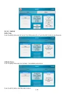
NOTE: Prime the calibrator bottle daily to remove air bubbles from the tubing and deliver fresh calibrator to the 
cal well!


When you have finished priming the fluid pumps, touch the [X] button to return to the Main display. 

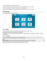
Stirbar 

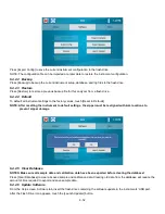
The StirbBar screen is used to adjust the speed of the stir bar.  

Note: The sample module must be full of buffer when adjusting stir speed. To fill the module with buffer, see 

6.2.2


Module

. 

Touch the [Off] button under Stirbar1 to change it to [On]. Verify the stir bar is rotating smoothly, but not jumping.  


If the stir bar is jumping, touch the [Edit] button and use the Down Arrow Button to decrease the stir speed until the stir bar 
is spinning smoothly. 

NOTE: Set the stir speed as high as possible without causing the stir bar to jump! 


Touch the [X] to return to the Service screen. 

Touch the Stirbar [On] button to change it to [Off]. The stir bar will stop. 

Touch the [Off] button again. Verify the stir bar is spinning smoothly and not jumping. If necessary, reduce the stir speed 
until the stir bar is not jumping. 

Touch the [On] button to stop the stir bar. 

After you have adjusted the stir speed, touch the [X] button to return to the Main display. 

Increase 
Speed 

Speed 

indicator 

Decrease 
Speed 

Summary of Contents for YSI 2500

Page 1: ...USER MANUAL 525021 YSI 2500 Biochemistry Analyzer OPERATIONS AND MAINTENANCE MANUAL...

Page 2: ...uffer Solution 4 7 Install Calibrator Solution 4 7 4 6 Prime the Fluid System 4 8 4 7 Install Enzyme Membranes 4 8 4 8 Configure Instrument 4 10 4 9 4 9 1 Assign Chemistries to Probes 4 10 4 9 2 Buffe...

Page 3: ...tle 8 1 8 2 3 Check the Buffer Bottle 8 2 8 2 4 Check for Leaks 8 2 8 2 5 Clean up Spills 8 2 8 2 6 Daily Operational Checks 8 2 Monthly Maintenance 8 2 8 3 8 3 1 Calibration Pumping System Maintenanc...

Page 4: ...2 Warranty and Repair 12 1 Limitation of Warranty 12 1 12 1 12 1 1 Shipping Instructions 12 1 12 1 2 Cleaning Instructions 12 2 YSI Factory Authorized Service Centers 12 2 12 2 13 Notices 13 1 Declara...

Page 5: ...ad options Save data on a USB drive send it over the network or access it in a searchable database anytime Onboard FAQs Minimizes operator learning curve General Specifications 1 2 Sample size Adjusta...

Page 6: ...Repairs are to be performed only by trained and approved personnel 6 This instrument must be connected to a protectively grounded earthed outlet 7 The following notice is provided in compliance with...

Page 7: ...nd or damage to equipment Attention consulter la documentation jointe Cette mise en garde indique qu une mauvaise utilisation de l instrument peut entra ner une blessure l g re ou grave chez une perso...

Page 8: ...of our authorized dealers sold the system to you call YSI Life Sciences Customer Service at 800 659 8895 or 937 767 7241 and we ll be happy to help you 1 After removing the instrument from the shippin...

Page 9: ...need repair What You Need 3 3 Several things are needed in order to analyze samples using the 2500 Analyzer The following list shows the basic items required 2500 Instrument with AC Power Cord Bottle...

Page 10: ...e Sipper senses fluid level to control immersion depth and detect errors Station 1 Plate and rack holder accepts most standard plates racks for batch sampling of up to 96 samples Station 2 Test tube h...

Page 11: ...ed when the Buffer or Calibrator Bottles are empty or when the Waste bottle is full Rear Panel Figure 3 5 Power Switch The main power switch is an on off rocker switch 0 off and I on located on the ba...

Page 12: ...terial holding the tubing to the right side of the instrument 3 Next connect bottle tubing and cables a Insert the large diameter waste tube into the hole in the waste bottle b Connect one end of a sh...

Page 13: ...strument then into a properly grounded electrical outlet provided with a 15 or 20 Amp circuit breaker The instrument will automatically adjust the voltage as needed If you are located outside the Unit...

Page 14: ...4 3 4 Since the top cover of the instrument is removed the message below will appear 5 Touch OK to confirm then touch the Settings icon 6 Touch the Interlocks On button...

Page 15: ...f the sipper while the instrument is in operation 1 Touch the Service icon 2 From the Sipper tab of the Service screen touch Home 3 Once the sipper has moved to the home position touch Module 1 4 The...

Page 16: ...Make certain the Sipper is centered then touch Save at the bottom of the adjustment window Sipper Adjustment Position Figure 4 2 7 To test the alignment of the sipper Touch Inject to lower the sipper...

Page 17: ...Select Module 1 The tip of the sipper should be right at the top of the module Use the arrow buttons to lower or raise the sipper until the tip of the sipper is even with the top of the module 10 Touc...

Page 18: ...Buffer 1 Place about 500 mL of reagent water distilled or deionized into a 1000 mL flask or other clean container 2 Add two packages of YSI 2357 powder buffer concentrate and stir 3 Add more reagent...

Page 19: ...ce screen touch the Module tab 2 Touch the button under B1 Pump to turn the buffer pump on 3 The instrument will prime the buffer solution 4 Once buffer flows from the end of the sipper touch the butt...

Page 20: ...inside with a few drops of salt solution YSI 2392 7 Place one drop of salt solution on the enzyme probe face 8 Using the plastic membrane holder press the O ring membrane assembly gently onto the prob...

Page 21: ...eters 4 9 1 Assign Chemistries to Probes 1 From the main display touch Configure 2 Touch the Probe A membrane button to select the chemistry you want to measure 3 The Probe A Membrane button will now...

Page 22: ...Use the default settings unless a particular application instruction specifies another value see Section 7 Chemistry Setup for details NOTE Changing chemistry assignments will change the calibrator v...

Page 23: ...nt values baseline They must be below 6 nA and stable 3 Check to see if they are decreasing in value 4 Check the sample module it should be full of buffer 5 If necessary touch the Flush Button to flus...

Page 24: ...o determine if your enzyme membranes are structurally intact 1 Pour a small amount of FCN standard 1000 mg dL in a test tube or multi well plate 2 From the Run Batch tab touch New 3 Choose from the se...

Page 25: ...button 8 Select the chemistries that require the FCN test 9 To change the Batch Name from the default value of TestBatch touch the TestBatch button The keypad window will appear 10 Type your new batc...

Page 26: ...4 For the daily linearity checks select only the chemistry that corresponds to the linearity standard in that sample location 15 Touch Save to save the batch 16 Create batches for each linearity solut...

Page 27: ...5 4 5 1 3 Results 20 Touch the Results tab 21 Select a sample location 22 Touch a chemistry to show details Select to show details Select a sample...

Page 28: ...tolerance refer to Section 10 Troubleshooting Chemistry Calibration Std Linearity Std Acceptable Range g L Glucose 2776 2 50 g L 1531 9 00 g L 8 55 to 9 45 L Lactate 2776 0 50 g L 1530 2 67 g L 2 54 t...

Page 29: ...uch as Batch Name separate name for this batch Dilution factor Units Multi Sample multiples of each sample location in this batch or Repeats multiples of the entire batch Please note that the instrume...

Page 30: ...o export and then touch Export 3 Previously exported plates can be imported later using the Import button NOTE Importing a plate with the same name overwrites an existing plate 5 3 3 Load Samples 5 3...

Page 31: ...r R8 tube rack into the cavity just inside the front door 3 Insert your sample tubes into the tube rack you installed Figure 5 3 5 3 4 Run Samples Touch Start to run the current batches The 2500 Analy...

Page 32: ...2 a Insert your sample tube into the tube holder Station 2 from below the spring clip b Slide it up all the way until it rests below the notch at the top The test tube holder accepts tubes sizes up t...

Page 33: ...ple you configured will be underlined 6 Touch Start to run the highlighted Stat or Syringe sample at Station 2 If a Station 1 batch is in progress the Stat sample will run as soon as the current sampl...

Page 34: ...5 11 8 The Stat sample results are displayed on the Run Stat tab Stat sample results...

Page 35: ...een includes System and Display tabs 6 1 1 System Touch the System tab if not already selected The System tab is used to adjust calibration settings enable sipper and bottle fluid detection and interl...

Page 36: ...l entered until it has been idle for 2 hours AND the Screensaver is active It will then calibrate every 4 hours performing a maximum of 3 calibration attempts each time to preserve reagent use If the...

Page 37: ...inutes Touch OK After you have finished making your changes touch the Save button 6 1 1 2 Sipper Options Touch the Sensitivity High button and change it to Low for samples with high conductivity Touch...

Page 38: ...Produce an error when no sample is detected no sample result Warn Use fixed depth when no sample is detected report a sample result 6 1 1 3 Sensors To change bottle Fluid Detection touch the button f...

Page 39: ...alysis or Calibration Reports touch the button below it to cycle through the selections Brief Detailed or None 6 1 2 2 Print Configuration Touch the Print Configuration button to send the current inst...

Page 40: ...brate Display button to enter touch screen calibration Using a stylus touch and hold the center of the red flashing that appears at each corner of the display until appears After you have held the in...

Page 41: ...Screensaver function by touching the OFF button and changing it to ON NOTE The Screensaver must be enabled On to allow the analyzer to conserve reagents by only calibrating every 4 hours performing a...

Page 42: ...60 next to Start after Enter the number of minutes that the instrument should remain idle before enabling the screensaver then touch OK Touch the Save button 6 1 3 Date Time To set the date time touch...

Page 43: ...or details on aligning the sipper with the sample module Always Home the sipper before performing alignment If necessary the sipper can also be aligned with Station 2 the different types of racks plat...

Page 44: ...pper at other locations touch the button under Location Touch the button for your location Station 2 for example Touch the Position button and use the arrow buttons to align the sipper with the select...

Page 45: ...Depth and select the location The sipper will move to the selected location Sample Module use the up and down arrows to set the tip of the sipper even with the top of the Module Refer to Section 4 4 A...

Page 46: ...uch the Aspirate button The pump plunger will retract about half way as it does when it aspirates a sample Note that the actual distance depends on the sample size setting Dispense Touch the Dispense...

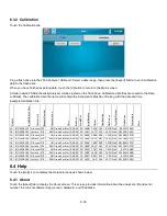
Page 47: ...3 Calibrate The 2500 Analyzer will automatically calibrate before running a sample batch You may initiate manual calibration from the Modules tab of the Service screen by touching the Calibrate butto...

Page 48: ...ump Touch the ON button under B1 pump The buffer pump will run Touch the OFF button to stop the pump Calibrator Pump Touch the ON button under Cal 1A Pump The calibrator pump will run Touch the OFF bu...

Page 49: ...ing smoothly but not jumping If the stir bar is jumping touch the Edit button and use the Down Arrow Button to decrease the stir speed until the stir bar is spinning smoothly NOTE Set the stir speed a...

Page 50: ...plates of sample data are displayed under the Plate tab Touch the scroll buttons to page through plates Touch a specific plate to highlight it then touch View to display the sample data for the selec...

Page 51: ...a Touch the sample result to show details Touch X to return to the Data screen 6 3 1 1 Plate Name Filter Touch the Name button and enter a plate name to filter the data Only plates that begin with tha...

Page 52: ...teauTempAdj PlateauSlope Temperature Errors Station2 0 MANUAL 9 14 2018 14 52 Complete Station2 Glucose Probe1A 2 4886 g L 0 00 30 25 2 27 19 35 2 27 17 08 16 92 0 022 22 08 Station2 0 MANUAL 9 14 201...

Page 53: ...aseline Plateau FinalBaseline NetPlateau CrossNetPlateau ProbeSlope Temperature Errors 1A 8 1 2018 10 12 Glucose 2747 1 8 GramsPerLiter 0 00 30 25 1 038 7 416 1 019 6 378 NaN 0 0233 23 62 1B 8 1 2018...

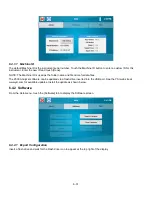
Page 54: ...me and file name for data files The 2500 Analyzer software can be updated via a flash drive inserted into the USB port See the YSI web site at www ysi com for available updates Install the update as s...

Page 55: ...values touch Reset to Defaults NOTE After resetting the instrument to default settings the sipper must be realigned with ALL locations to prevent sipper damage 6 4 2 5 Clear Database NOTES Make sure a...

Page 56: ...ar all sample data After updating the software the sipper must be aligned with all positions FAQ From the Help menu touch the FAQ tab to display frequently asked questions and answers Connectivity 6 5...

Page 57: ...ne or more 2500 Analyzer instruments to a router DHCP server via the RJ45 Ethernet port Accessing Stored Data Access the data stored in a 2500 Analyzer connected to a LAN or router via ftp See 6 4 1 A...

Page 58: ...ple and calibration data files are stored in the Samples folder of the 2500 Analyzer The file names are BioSample_Machine ID csv BioCalibration_Machine ID csv 6 5 2 RS232 Port The RS232 serial port su...

Page 59: ...unt for any interferences to your reading Methods to do these corrections are described below Once you make the above determinations you can decide whether one of the standard setups described below w...

Page 60: ...onversion if concentration unit conversion is required Special Considerations If sample dilution is required use reagent water If a solution must be prepared from solid glucose use the following dilue...

Page 61: ...ple Size 25 L End Point 30 sec Precision CV n 10 2 or 0 03 g L whichever is greater Linearity 2 or 0 03 g L whichever is greater 0 05 to Cal Point 5 Above Cal Point to Range Max Typical Working Life 1...

Page 62: ...w to set up your instrument for simultaneous determination A Probe B Probe Chemistry Glucose L Lactate System Buffer YSI 2357 Calibrator Std YSI 2776 Linearity Std YSI 1531 YSI 1530 Membrane YSI 2365...

Page 63: ...nzyme probes with isopropanol only rinse with authorized rinsing agent see Section 8 1 Clean up all spills then reassemble Daily Maintenance 8 2 8 2 1 Empty the Waste Bottle Carefully pull the waste t...

Page 64: ...System Maintenance Prepare about 100 mL of one of the authorized cleaning solutions see Section 8 1 and place this solution in a clean calibrator bottle Install the bottle in the calibrator bottle pos...

Page 65: ...dry the bottle caps Dry the SMA connector thoroughly with a lint free tissue For best results let air dry for 2 hours 8 3 4 Sample Module Cleaning For applications requiring more frequent cleaning of...

Page 66: ...hex screws from the top of the waste module Disconnect the calibrator and waste tubing and remove the waste module from the base plate Figure 8 2 Immerse the waste module in authorized disinfecting a...

Page 67: ...ment Replace the Sipper Pump seals every 6 months Heavy usage may warrant more frequent replacement Disconnect the tubing from the Sipper Pump Remove the two hex screws from the Sipper Pump head and r...

Page 68: ...the pump head and the drive hub 8 4 5 Bottle Tubing Disconnect the tubing and unscrew the cable connectors from the buffer waste and calibrator bottles on each side of the instrument Lift the bottle t...

Page 69: ...alibrator pump tubing should be replaced at least every 6 months or 1000 hours sample ready NOTE The buffer pump tubing and calibrator pump tubing each require a different type of grease It is importa...

Page 70: ...s on the left side of the pump Place the blue pump head cover onto the buffer pump and press until it snaps into place Connect Buffer Tubing Connect the small diameter tubing from the Buffer Pump to t...

Page 71: ...ng agent Install the sample module Remember to install the stir bar and the module seal O ring Secure the sample module using the three thumb nuts Install a new O ring on the temperature probe then in...

Page 72: ...Carefully insert the long thin end of the new sipper and slide it into the mounts Slide the sipper cone up the sipper and screw it into the sipper arm Be sure the sipper is centered in both mounts Tig...

Page 73: ...the 2500 Analyzer New fuses may be purchased from YSI or obtained from many local electrical component suppliers Be sure to obtain the correct fuse rating as indicated below CAUTION UNPLUG THE INSTRU...

Page 74: ...horoughly empty the bottles reinstall them in the instrument and prime the system with air After all the fluid has been pumped from the system drain the sample module by temporarily removing one probe...

Page 75: ...allation dates Compare the elapsed time to the recommended time Look and listen for problems fluid leaks salt build ups air bubbles in the sample module loose connections noisy components etc Review S...

Page 76: ...Test Batch 1 1A Glucose 2 50 g L Analyte P96_A01 IB nA 1 79 NPL nA 17 63 1A Glucose 4 82 g L FB nA 1 51 IB nA 2 11 PL Slope nA m 0 42 NPL nA 32 65 IB Shift 0 65 PL Slope nA m 0 69 NPL Shift 3 64 Temp...

Page 77: ...cannot adequately flush the sample module PL Slope Slope of the plateau The slope is reported in nanoamps per minute A newly installed membrane may have an elevated plateau slope An excessive slope c...

Page 78: ...robe ACTION Enter probe diagnostics and check probe currents SECTION 6 2 2 Module POSSIBLE CAUSE Power disruption ACTION Enter probe diagnostics and check probe currents SECTION 6 2 2 Module POSSIBLE...

Page 79: ...e current nA ACTION Dilute sample or adjust sample size down and repeat SECTION 7 1 Sample Volume SYMPTOM MEASUREMENT ERROR PL Slope POSSIBLE CAUSE Stir speed too fast or too slow ACTION Adjust stir s...

Page 80: ...ols Stirbar POSSIBLE CAUSE Newly installed enzyme membrane ACTION Enter probe diagnostics and check probe currents SECTION 6 2 2 Module POSSIBLE CAUSE Newly installed probe ACTION Enter probe diagnost...

Page 81: ...f sipper with isopropyl alcohol and a lint free tissue POSSIBLE CAUSE Sipper mounting screws loose ACTION Check sipper mounting screws and tighten gently if required SECTION 8 4 10 Sipper Replacement...

Page 82: ...SYMPTOM ERROR Temperature POSSIBLE CAUSE Ambient temperature too cold or hot ACTION Operate at ambient temperatures between 15 and 35 C SYMPTOM Printer Does Not Advance POSSIBLE CAUSE Paper or roll j...

Page 83: ...oxidized at the platinum anode producing electrons Reaction 2 A dynamic equilibrium is achieved when the rate of H2O2 production and the rate at which H2O2 leaves the immobilized enzyme layer are cons...

Page 84: ...pared to the initial baseline value iib during the flush cycle If a significant shift is detected the sample module continues to be flushed with buffer As soon as the baseline recovers buffer flushing...

Page 85: ...over product enzyme kinetics defines the response and nonlinearity is a symptom This occurs as an enzyme membrane ages It is necessary to periodically check sensor linearity YSI offers linearity stand...

Page 86: ...NY DEFECTIVE PRODUCT COVERED BY THIS WARRANTY To exercise this warranty write or call your local YSI representative or contact YSI Customer Service in Yellow Springs Ohio Send the product and proof of...

Page 87: ...5 Lysol if this is more convenient to the user Autoclavable products may be autoclaved 2 The user shall take normal precautions to prevent radioactive contamination and must use appropriate decontami...

Page 88: ...13 1 13 Notices Declaration of Conformity 13 1...

Page 89: ...rference by one or more of the following measures Reorient the receiving antenna Relocate the computer with respect to the receiver Move the computer away from the receiver Plug the computer into a di...

Page 90: ...me Multi Sample Batch Repeats Dilution Chemistries Units Status Module Printout Results Run Stat Configure Stat Configure Syringe Data Plate View Date Filter Export Calibration Date Export Settings Sy...

Page 91: ...2 50 g L 1000 mg g 2 50 1000 mg L 2500 mg L w v 2 50 g L 2 50 g L 0 1 L dL 2 50 0 1 g dL 0 250 g dL 0 250 Note g dL is g 100ml or percent mmol L 2 50 g L 2 50 g L 1 mole 180 g 1000 mmole mole 2 50 1 1...

Page 92: ...excluded from the probe by the cellulose acetate layers of the membrane However thymol phenols anilines hydrazines and hydrazides hydroxylamines oximes and a few other compounds of molecular weight be...

Page 93: ...ed to cause an error of 1 mmol l in the lactate reading or 5 mg dl in the glucose reading Certain exogenous substances can interfere with measurements The YSI 2500 should not be used to analyze specim...

Page 94: ...0 Tolbutamide 270 34 2200 81 D Xylose 150 13 730 49 RADIOPAQUES Meglumine lodipamide 1335 02 25000 190 Meglumine lothalamate 809 13 29000 360 Renografine Squibb mixture 22000 220 gm 1 Sodium Methioda...

Page 95: ...45 5 2 54 Guaiacol 124 14 12 5 1 01 Hydrazine Sulfate 130 12 28 2 15 Hydrogen Peroxide 34 01 0 2 0 05 Hydroquinone 110 11 3 7 0 3 Hydroxylamine Hydrochloride 69 49 0 3 0 04 D Idose 180 16 167 9 27 Is...

Page 96: ...17 1 17 Appendix D Line Power Cord and Plug Wiring United Kingdom United States Europe...

Page 97: ...Glucose 1 78 g L L Lactate 2776 Dual Standard 2 50 g L Glucose 0 50 g L L Lactate Calibrator 2777 Dual Standard 25 0 g L Glucose 2 50 g L L Lactate 2751 Printer Paper 5 rolls 2901 Printer Includes po...

Page 98: ...sed conserved and re used in the future is central to our work Our products and services move treat analyze monitor and return water to the environment in public utility industrial residential and com...

Reviews: