


14
Version 1 – GBR (05/05/2020)
D-502-0173
4.
Regulation - unit control
4.1.
General information - safety
-
Regulation is integrated into the body of the unit. Any manipulation other than specified in this manual
is prohibited.
-
All control elements located on the body of the unit, which are designed for user control, are powered
by 10VDC (safe voltage).
4.2.
Controls
4.2.1.
Main control panel
4.2.1.1.
Main control - knob
(position 1)
-
The main control (know) allows for continuous adjustment of the power of the unit in any position from
the minimum to maximum power according to the user's requirements.
-
The "OFF" position switches the entire unit off.
-
The "OFF" position does not disconnect the unit from the power supply (the unit may be disconnected
from the mains using the main switch located on the back of the unit or by unplugging the power cord
from the power outlet)
4.2.1.2.
Signal diode
-
Indicates operation of the unit. If the LED is ON, the unit is active. If it is not lit, the unit is turned off
4.2.1.3.
Indicator of filter box clogging - signalisation of need for filter box replacement
-
The orange indicator activates when the filter box is clogged. At the same time, it informs the user about
the need to replace the filter box (box replacement is described in the chapter 7.1.2. filter box
replacement).
-
The indicator activates automatically depending on the current, actual clogging of the filter box, which is
set by the manufacturer.
-
One of the parameters that affect the activation of the indicator is also power-flow the whole unit is
operated at. In general, the smaller the power-flow of the unit, the longer the time for indicator activation
(the less air is filtered).
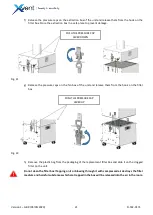
1. MAIN CONTROL (KNOB)
2. SIGNAL LED
3. FILTER CLOGGING WARNING INDICATOR
1
2
3
Fig. 12