Operation Manual
60
Operation
Fork Positioning Carriage Operation
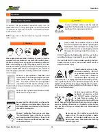
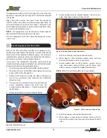
Caution
Do not adjust forks when the carriage is loaded. Adjusting
forks when carriage is loaded may result in loss of load or
carriage damage. Always use Fork Positioning (Aux Control)
buttons to adjust the forks BEFORE loading the carriage.
Quick Attach System
This Telehandler includes a quick attach system that allows for
easy attachment changes. Perform attachment connection
and removal procedures on level ground.
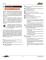
Warning
Improper connection of an auxiliary
attachment can result in death or serious
injury. Attachments not locked into place could
become unstable and fall on the operator or
other personnel near the Telehandler, which
could result in death or serious injury.
•
Make sure attachment locking devices are always in
place.
•
DO NOT operate the Telehandler until you have positive
indication that the carriage attachment is fully engaged.
Attachment Connection
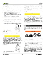
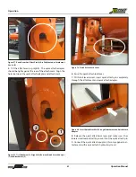
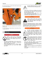
Figure 76. Drive Telehandler Forward to Align Pivot Pins (A) with Attach-
ment Hooks (B)
1. Position the Telehandler directly behind the attachment.
NOTE:
Allow enough distance to extend the boom ap-
proximately 18 to 20 inches.
2. Tilt the quick attach adapter forward.
3. Extend the boom and/or drive the Telehandler forward
until the pivot pins (A) are below and between the two (2)
attachment hooks (B).
4.
Raise the boom until pivot pins (A) have seated fully in at-
tachment hooks (B).
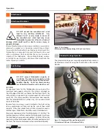
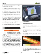
To move the forks outward, press the Aux Control top button
(1) on the front of the joystick. To move the forks inward, press
the lower button (2) on the front of the joystick.
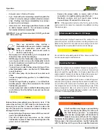
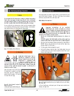
Hydraulic attachments have a
maximum hydraulic pressure
rating. Failure to make sure the
attachment is equipped with
a pressure reducing valve, or
is rated to be equal or greater than 3,500 psi, which is the
maximum pressure of the Telehandler auxiliary hydraulic
system at the quick-disconnect couplers, could result in
death or serious injury.
Warning
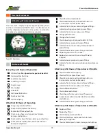
When the Attachment Tilt Control
Thumbstick is moved, it activates
hydraulic pressure through the
quick attach couplers (A) and (B)
to move the carriage.
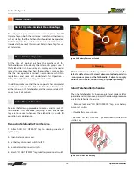
Figure 75. Quick Attach Couplers For
Hydraulic Systems.
(A) Female Coupler. (B) Male Coupler.
A
B
1
2
18408-001
AUX
CONTROL
AUX
CONTROL
FORK TILT
DOWN
FORK TILT
UP
JOYSTICK
ENABLE
BOOM
RETRACT
SWAY
LEFT
BOOM
EXTEND
SWAY
RIGHT
SW
AY
ENABLE
BOOM
LOWER
BOOM
RAISE
Figure 74. Auxiliary Control Buttons
A B

