Operation Manual
32
Operator Cab
Warning
A brief description of controls, indicators, and
instruments is provided as a convenience for
the operator. These descriptions DO NOT pro-
vide complete operation instructions. Read
and understand the entire manual to pre-
vent death, serious injury, or equipment damage.
Ignition Switch
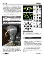
A key is required to operate the ignition switch.
Figure 11. Key and Ignition Switch
The ignition switch has three (3) positions: OFF, RUN, and
START.
Ignition Switch
Position
Purpose
OFF
Shuts down entire electrical system, except
the horn and accessory outlet.
RUN
All controls and indicators are operable.
START
Engages starter motor to crank engine.
NOTE: The START position is spring-loaded. When the key is
released, the Ignition switch will automatically return to the
RUN position.
Accessory Outlet
A 12 volt accessory outlet is provided as a power source for
personal items, such as a radio or cell phone.
Figure 12. Accessory Outlet
Accelerator Pedal
Press the accelerator pedal to increase engine speed. The ac-
celerator pedal is spring-loaded to return to idle speed.
Figure 13. Accelerator Pedal
A key is required to operate the ignition switch.
Operator Cab


