background image

Technical Support US:  888-443-2751 

Technical Support INTL:  316-943-2751 


37 

OVEN MAINTENANCE 


* Do not use caustic cleaners on the control panel. Only use cleaners compatible with 
Lexan® on the face of the Large User Interface or Oven Controls. 


* Do not use caustic cleaners on conveyor bearings. 


* Do not use water jet to clean ovens. 


Contact a factory representative or a local service company to perform all other mainte-
nance and repairs. 


As with any appliance, periodic maintenance is required. Many factors affect this schedule 

such as product mix and hours of usage. An example schedule is included. 

Oven must be cool and all power to the oven turned off before any cleaning is done. 

DANGER 

Cleaning

Empty Crumb Trays

Wipe down Front, Sides, & Top

Wipe down Control Box & Control Panel *

Run Self Clean Mode

Clean Fan Filters

Remove large debris from Conveyor

Remove debris from inside Bake Chamber

Clean grease trays inside Bake Chamber

Clean Heating Elements

Clean inside Bake Chamber

Clean Conveyor Assembly

Inspection

Check Fan Filters for dirt

Check Conveyor Wire Belt for Stretch

Check Conveyor Drive Roller Chain for Stretch

Adjust

Conveyor Wire Belt

Lubricate

Conveyor Drive Roller Chain

Replace

Fan Filters

Oven Maintenance Schedule

Daily Weekly Monthly

Semi-

Annual

Summary of Contents for SmartSolutions 2336

Page 1: ...llowing XLT Radiant Oven Versions Standard S A World W A 2000887 Current versions of this manual Rough In Specifications Parts Service Manual Architectural Drawings a list of International Authorized Distributors are available at www xltovens com XLT Radiant Oven Installation Operation Manual Read This Manual Before Using This Appliance Original Instructions ...

Page 2: ...ion 25 Oven Ventilation Guidelines 27 Oven Initial Start Up 28 Oven Operation 29 Oven Operator Controls 30 Oven Cleaning 34 Oven Maintenance 37 Oven Troubleshooting 38 Electrical Schematics 39 Certifications 43 Oven Start Up Checklist 45 Notes 47 TABLE OF CONTENTS Revision Comments Date B Updated Oven Operating Temperature Range Table Pg 29 Updated Oven Operator Controls High Temp Description Pg 3...

Page 3: ...d We have witnessed store operators and building owners lose many thousands of dollars in lost revenue due to incorrect installations We highly recommend you follow all instructions given in this manual as well as follow best practices in plumbing electrical and HVAC building codes Definitions Symbols A safety instruction message includes a Safety Alert Symbol a signal word or phrase such as DANGE...

Page 4: ...s appliance needs an unobstructed flow of fresh air for satisfac tory operation must be installed in a suitably ventilated room in accordance with current regulations This appliance should be serviced by qualified person nel at least every 12 months or sooner if heavy use is expected CAUTION This appliance is not intended for use by persons including children with re duced physical sensory or ment...

Page 5: ...wer as des ignated on the nameplate label located on the side of the unit Minimum clearances must be maintained from combustible non combustible construction materials Follow all local codes when installing this unit Follow all local codes to electrically ground the unit Appliance is not to be cleaned with high pressure water XLT ovens are certified for use in stacks of up to four 4 units of XLT p...

Page 6: ...Operations Manual furnished with the unit This warranty shall not excuse the owner from properly maintaining the equipment in accordance with the Installation Operation Manual furnished with the unit A copy of the Initial Start Up Checklist must be filled out and returned to XLT when the unit is initially installed and or when the unit is removed and installed in another location The electric util...

Page 7: ... not excuse the owner from properly maintaining the equipment in accordance with the Installation Operation Manual furnished with the unit A copy of the Initial Start Up Checklist must be filled out and returned to Distributor Service Provider and XLT when the unit is initially installed and or when the unit is removed and installed in another location The electric utilities must be connected to t...

Page 8: ...set in place X Ovens moved and stacked with proper lifting equipment X Peel all PVC X Connect cord anchorage to incoming electrical supply X Connect electrical supply X Connection may require Permit and Code Inspections X Relocate Make Up Air to enter the room at the ends of the ovens X Start up per XLT Installation Operation Manual X Verify oven functions adjust as necessary X Responsibility Serv...

Page 9: ...at can provide assistance on any type of XLT equipment problem you may experience Tech nical support is available 24 7 365 or visit www xltovens com NOTIFY CARRIER OF DAMAGE AT ONCE Save this Manual This document is the property of the owner of this equipment XLT reserves the right to make changes in design specifications and or make additions to or improvements to its product without imposing any...

Page 10: ...nd uniform food cooking The conveyors can be easily configured to move either left to right or right to left with a simple programming change Precise temperatures are user adjustable and maintained by a digital control An easily removable front panel allows the full cleaning of the oven interior All exposed oven surfaces both exterior and interior are stainless steel The conveyor is a three piece ...

Page 11: ...cal Support INTL 316 943 2751 11 OVEN DESCRIPTION Control Box Crumb Tray Front Panel Conveyor Locking Swivel Caster Oven Lid Control Box Lid Chain Guard Control Panel Oven Control Manual Drawer Large User Interface Product Stop Conveyor Flap ...

Page 12: ...Cordless Std 1 5 8 1 3 4 1 Gearwrench QTY Bits QTY 11 16 1 5 16 1 6 2 Phillips 1 13 16 1 3 8 1 3 16 Drill Bit 1 7 8 1 7 16 1 5 32 Drill Bit 1 15 16 1 1 2 1 10 24 Tap 1 1 1 9 16 1 8 32 Tap 1 3 8 Drive Allen 5 8 1 1 8 1 11 16 1 Miscellaneous QTY 3 16 1 3 4 1 Volt Amp Meter 1 7 32 1 Heat Probe 1 1 4 1 Screw Drivers QTY Molex Extractor 1 5 16 1 2 Phillips 1 Molex Crimper 1 3 8 1 1 Phillips 1 Straight ...

Page 13: ... 3 8 2134 756 1686 2336 International WoodCrate Dimensions Oven Model Electric Ovens X Y Z Z With Oven 85 3 4 31 3 4 13 1 2 59 3 4 2178 806 343 1518 2336 Oven Model Electric Oven Domestic WoodCrate Dimensions X Y Z Z With Oven 57 3 8 22 6 1 2 52 3 4 1457 559 165 1340 Metal SkidDimensions Oven Model Electric Oven 2336 NOTE All dimensions in inches millimeters 1 4 6 unless otherwise noted ...

Page 14: ...Technical Support US 888 443 2751 Technical Support INTL 316 943 2751 14 OVEN DIMENSIONS WEIGHT ...

Page 15: ...1760 2154 2077 1959 584 914 1187 1784 1664 1721 686 1080 1473 798 978 943 889 INTL WOOD DOM WOOD METALSKID 23 36 46 3 4 70 1 4 65 1 2 69 3 4 13 1 2 29 44 1 2 60 2243 2768 2666 2508 584 914 1187 1784 1664 1772 343 737 1130 1524 1017 1256 1210 1138 J 2336 CRATED WEIGHT CRATED WEIGHT CRATED WEIGHT QUAD STACK A B C D E F G H K OVEN WEIGHT 2336 N A J K OVEN WEIGHT TRIPLE STACK A B C D E F G H K OVEN WE...

Page 16: ...onnections must meet all local code requirements Ensure ovens are grounded per local codes Incoming Power Connection Point Control Box Rear Standard Volts AC Amps Hertz Phase KW Volts AC Amps Hertz Phase KW 2336 31 27 9 6 24 10 5 Electric Oven Electrical Requirements Per EACHOven Oven Model STANDARD WORLD 380 50 3 208 240 60 3 4 Wire Service L1 L2 L3 5 Wire Service L1 L2 L3 N 2 Grounds per oven 1 ...

Page 17: ...he ovens These ovens are suitable for installation on either combustible or non combustible floors and adjacent to either combustible or non combustible walls The minimum clearances are 2in 51mm measured from the exit end of the conveyor the rear panel of the oven and from the control panel NOTE All dimensions in inches millimeters 1 4 6 unless otherwise noted 2 00 51 From back of oven to wall 2 0...

Page 18: ...local building and mechanical codes It is required that the ovens be placed under a ventilation hood to provide exhaust ventilation and adequate air supply Disconnect Switch Breaker Panel Shown for reference only NOTE Equipment must be installed with cord anchorage to relieve strain on conductors twisting of terminals and abrasions to insulation ...

Page 19: ...Technical Support US 888 443 2751 Technical Support INTL 316 943 2751 19 OVEN ASSEMBLY Base Assembly Quad Stack Base Assembly Single Double Triple Stack ...

Page 20: ...GER Make sure that the notch on tube of the winch assembly is aligned with the pin in the tripod base as shown These alignments are important and keep the jack aligned properly Check for smooth operation The cable should not be pinched and should pass smoothly over the pulley on top of the pole assembly Inspect cable prior to each use If cable is frayed or shows signs of excessive wear and tear DO...

Page 21: ...hnical Support INTL 316 943 2751 21 OVEN ASSEMBLY 2 3 The Lifting Pipe hole marked for the appropriate oven size must be installed closest to the control box NOTE The folding leg of the tripod must be positioned outwards from the oven NOTE ...

Page 22: ...the Lifting Pipe properly and completely will result in damage injury or death from a falling oven DANGER Both jacks should be raised in unison otherwise they may bind and a dangerous situation will develop Do not put any part of yourself under the oven at any time The Oven is top heavy Be careful DANGER Stacking the Ovens 6 4 5 ...

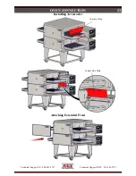
Page 23: ...Technical Support US 888 443 2751 Technical Support INTL 316 943 2751 23 OVEN CONNECTION Attaching Extended Front Installing Accessories Conveyor Flap Control Box Plate ...

Page 24: ...e configured with a re straint to limit the movement of the oven without depending on the electric power supply cord to limit the oven movement One 1 restraint kit which includes one 1 eye bolt one 1 stainless steel clip a cable is required for each oven stack regardless if used on a single double triple or quad configuration The clip should be installed in the lowest hole of the back wall on the ...

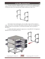
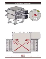
Page 25: ... existing holes that simplify installation and future service OVEN FIRE SUPPRESSION This design has been tested and approved to successfully comply with fire suppression codes It uses only two 2 nozzles per bake chamber and allows crumb trays chain guards and all other accessories to be easily removed The kit does not interfere with any operations or maintenance For detailed information regarding ...

Page 26: ...Technical Support US 888 443 2751 Technical Support INTL 316 943 2751 26 OVEN FIRE SUPPRESSION ...

Page 27: ...a pan on the conveyor belt at the center of the oven Observe the smoke pattern coming out of the oven Repeat the smoke candle test for each oven as well as when all ovens are operating The ventilation hood must capture all of the smoke from the oven Ventilation Guidelines Obtain information from the authority having jurisdiction to determine the requirements for your installation Your ventilation ...

Page 28: ...to XLT and the Author ized Distributor to initiate Warranty Policy If the Start Up Checklist is not filled out completely and returned to XLT the Warranty will not be honored Start up Procedure 1 Ensure that all ovens have been installed in accordance with the Installation Operation Man ual and that all utilities are connected to the ovens in compliance with local building codes 2 Fill out Step 1 ...

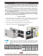
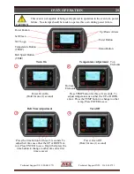
Page 29: ...P or DOWN arrow Press the TEMP button to change to other temp Press ENTER to save 2 3 CAUTION Power Oven On Hold for one 1 second Belt Time Adjustment Power Oven Off Hold for one 1 second Turn On Turn Off Power Button XLT Logo Temperature Button TEMP Belt Speed Button TIME Menu Button Enter Button Up Down Arrows Self Clean Top Elements Bottom Elements Press the time button for three 3 seconds To a...

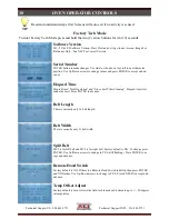
Page 30: ...is currently only 36 belt length Belt Width There is currently only 23 belt width Split Belt MC1 is for left belt and MC2 is for right belt Factory default is NO To change press ENTER Use Up Down arrows to change to YES still flashing Press ENTER to ac cept and advance Factory Tech Mode To enter Factory Tech Mode press and hold the two 2 arrow buttons for ten 10 seconds TIP Read and understand ste...

Page 31: ...ange the settings and then press ENTER to accept and advance The wire belt is non directional and doesn t phys ically need changed Beeper Button Test Press ENTER to enter setting A beep with each press of a button Press ENTER to exit Menu Mode Optional Menu Operation 1 To enter Menu Mode press MENU 2 The number in the lower right hand corner will begin flashing 3 Scroll through the menus by pressi...

Page 32: ... the self clean operation press the self clean button After you give confirmation the oven will increase temperature to 1000 F 538 C and hold for one 1 hour to burn off any food product that has accumulated on the heating panels Once the hour is over the oven will automati cally shut off It is not recommended to leave the oven unattended while the self clean operation is in process Oven Control LE...

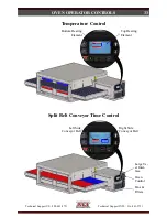
Page 33: ...Support INTL 316 943 2751 33 OVEN OPERATOR CONTROLS Oven Control Fans Filters Large Us er Inter face Split Belt Conveyor Time Control Right Side Conveyor Belt Left Side Conveyor Belt Top Heating Element Bottom Heating Element Temperature Control ...

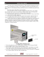
Page 34: ...ners on the control panel and or electronic components Only use cleaners compatible with Lexan on the face of the Large User Interface or Oven Controls The most critical items to be cleaned are the filters on the cooling fans The filters are held in place by the stainless steel fan guard filter mount and can be washed several times Regular cleaning of the filters is important to maintain air circu...

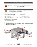
Page 35: ...ation 7 Connect restraint 8 Lock Casters 9 Plug in electric cord if equipped 10 Turn on main electrical disconnect 11 Follow normal starting instructions Oven must be cool and all power to the oven and hood turned off before any clean ing or maintenance is done DANGER If the oven is to be removed from its installed location for cleaning or servicing the following procedure is to be followed CAUTIO...

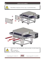
Page 36: ...INTL 316 943 2751 36 OVEN CLEANING 4 5 Front Panels can weigh up to 27 lbs 13 kg Use caution when lifting CAUTION 6 DO NOT spray liquid cleaning agents in the slots and holes in the following loca tions Rear of Control Box Underneath Control Box CAUTION ...

Page 37: ...roduct mix and hours of usage An example schedule is included Oven must be cool and all power to the oven turned off before any cleaning is done DANGER Cleaning Empty Crumb Trays Wipe down Front Sides Top Wipe down Control Box Control Panel Run Self Clean Mode Clean Fan Filters Remove large debris from Conveyor Remove debris from inside Bake Chamber Clean grease trays inside Bake Chamber Clean Hea...

Page 38: ... may affect the cooking performance and characteristics Oven temperature generally affects color Conveyor speed generally affects doneness The type of pan used Raw ingredient temperature frozen XLT ovens can be configured to cook a wide variety of food items We encourage you to experiment by trying different temperatures and belt speeds XLT can assist you with your oven product configurations 1 Ve...

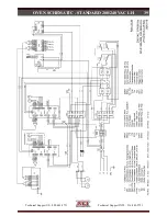
Page 39: ...Technical Support US 888 443 2751 Technical Support INTL 316 943 2751 39 OVEN SCHEMATIC STANDARD 208 240 VAC LH ...

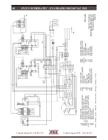
Page 40: ...Technical Support US 888 443 2751 Technical Support INTL 316 943 2751 40 OVEN SCHEMATIC STANDARD 208 240 VAC RH ...

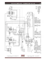
Page 41: ...Technical Support US 888 443 2751 Technical Support INTL 316 943 2751 41 OVEN SCHEMATIC WORLD 380 VAC LH ...

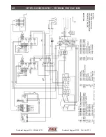
Page 42: ...Technical Support US 888 443 2751 Technical Support INTL 316 943 2751 42 OVEN SCHEMATIC WORLD 380 VAC RH ...

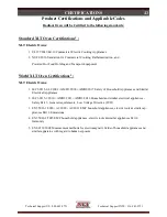
Page 43: ... 2017 Safety of Household Appliances and Similar Electrical Appliances 2 IEC 60335 1 2010 AMD1 2013 AMD2 2016 Household and similar electrical appliances Safety Part 1 General requirements Low Voltage Directive LVD 3 EN 55014 1 2006 A1 2009 A2 2011 EMC household appliances electric tools similar ap pliances Part 1 Emmisions 4 EN 55014 2 2015 EMC household appliances electric tools similar applianc...

Page 44: ...Technical Support US 888 443 2751 Technical Support INTL 316 943 2751 44 This page intentionally left blank ...

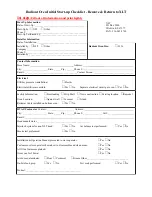
Page 45: ... No 1st step Fill out all information and print legibly Radiant Oven Initial Start up Checklist Remove Return to XLT Installation Operation Manual presented to store operator Yes No Customer or store operator shown how to disassemble and clean ovens Yes No All Oven features explained Yes No Ovens ran for 30 min Yes No Air born contaminates Flour Cornmeal Grease Other ______________________________...

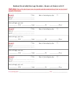
Page 46: ..._ Remove heater shipping clips Electrical Supply per oven Volts Amps Hz Phase Oven 1 N A Model __________________________________ Serial __________________________________ Remove heater shipping clips Electrical Supply per oven Volts Amps Hz Phase Oven 2 N A Model __________________________________ Serial __________________________________ Remove heater shipping clips Electrical Supply per oven Vo...

Page 47: ...Technical Support US 888 443 2751 Technical Support INTL 316 943 2751 47 NOTES ...

Page 48: ...XLT Ovens PO Box 9090 Wichita Kansas 67277 US 888 443 2751 FAX 316 943 2769 INTL 316 943 2751 WEB www xltovens com ...

Reviews: