


Technical Support US: 888-443-2751
Technical Support INTL: 316-943-2751
24
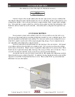
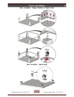
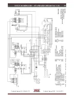
OVEN CONNECTION
Physical Location & Spacing Requirements
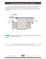
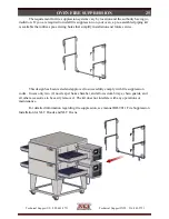
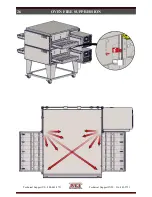
These ovens are suitable for installation on either combustible or non-combustible floors,
and adjacent to either combustible or non-combustible walls. The minimum clearances are
2in./51mm, measured from the exit end of the conveyor and from the rear panel of the oven, and
6in./152mm from the control panel.
All installations must conform to local building and mechanical codes.
NOTE
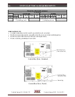
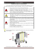
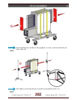
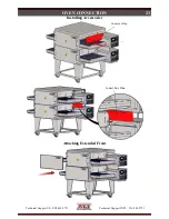
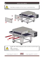
Because all ovens are equipped with casters, all installations must be configured with a re-
straint to limit the movement of the oven without depending on the electric power supply cord to
limit the oven movement. One (1) restraint kit, which includes one (1) eye bolt, one (1) stainless
steel clip & a cable, is required for each oven stack, regardless if used on a single, double, triple, or
quad configuration. The clip should be installed in the lowest hole of the back wall on the control
end of the lowest oven in the stack. The lag eye bolt must be installed into a structural member of
a wall or the floor. It is the owner’s responsibility to ensure the restraint is installed correctly.
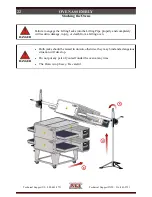
Upon completion of performing any service or cleaning functions that require removal of
the restraint, insure that it is correctly re-attached to the oven.
Restraint
1
2


