


ZCU102 Evaluation Board User Guide
89
UG1182 (v1.2) March 20, 2017
Chapter 3:
Board Component Descriptions
PS-Side: GTR Transceivers
[
, callout 1]
The PS-side GTR transceivers are shared through on-board bidirectional 2:1
multiplexer/de-multiplexer switches U125-U128 (Pericom PI2DBS6212
) capable of
6.5 Gb/s operation (see
).
The external GT-switch selection must be set by the user to ensure consistency with the
ZU9EG's internal GT interconnect matrix (ICM) settings. There are PS-side MIO GPIO(s) that
control the Pericom GT switch settings via PS-side I2C0 and the external GPIO port
expander.
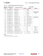
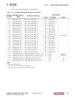
The functionality of each ZU9EG GTR lane is controlled through the MPSoC's ICM and is
defined in the
Zynq Ult MPSoC Technical Reference Manual
(UG1085)
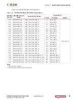
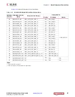
lists the interconnect matrix (ICM).
lists the interconnect matrix
settings and GTR lane functionality.
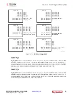
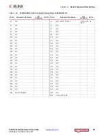
X-Ref Target - Figure 3-36
Figure 3-36:
Pericom GTR Switch Block Diagram
A0+
B0+
A0-
B0-
A1+
B1+
A1-
B1-
C0+
C0-
C1+
C1-
SEL
GND
B0+
1
24
NC
B0-
2
23
SEL
B1+
3
22
A0+
B1-
4
21
A0-
GND
5
20
A1+
V
DD
6
19
A1-
C0+
7
18
NC
C0-
8
17
V
DD
C1+
9
16
GND
C1-
10
15
V
DD
GND
V
DD
GND
V
DD
GND
V
DD
GND
Function
SEL
A to B
L
A to C
H
Block Diagram
Pin Description
Truth Table
28 27 26 25
11 12 13 14
;


