


ZCU102 Evaluation Board User Guide
29
UG1182 (v1.2) March 20, 2017
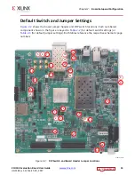
Chapter 3:
Board Component Descriptions
The ZCU102 DDR4 SODIMM interface adheres to the constraints guidelines documented in
the PCB Guidelines for DDR4 section of
UltraScale Architecture PCB Design Guide
(UG583)
The ZCU102 DDR4 SODIMM interface is a 40
Ω
impedance implementation. Other
memory interface details are also available in the
UltraScale Architecture FPGAs Memory
Interface Solutions Guide
(PG150)
DDR4 Component Memory
[
, callout 3]
The 4 Gb, 16-bit wide DDR4 memory system is comprised of one 256 Mb x 16 SDRAM
(Micron MT40A256M16GE-075E) at U2. This memory system is connected to the PL-side
XCZU9EG bank 64. The DDR4 0.6V VTT termination voltage is supplied from sink-source
regulator U35. The connections between the DDR4 memory and XCZU9EG bank 64 are
listed in
AN28
DDR4_SODIMM_CS0_B
149
CS0_N
AL30
DDR4_SODIMM_CS1_B
157
CS1_N
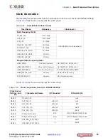
Table 3-4:
DDR4 Component Memory Connection to the XCZU9EG MPSoC
XCZU9EG
(U1) Pin
Net Name
I/O Standard
DDR4 Component Memory
Pin Number
Pin Name
AM8
DDR4_A0
SSTL12_DCI
P3
A0
AM9
DDR4_A1
SSTL12_DCI
P7
A1
AP8
DDR4_A2
SSTL12_DCI
R3
A2
AN8
DDR4_A3
SSTL12_DCI
N7
A3
AK10
DDR4_A4
SSTL12_DCI
N3
A4
AJ10
DDR4_A5
SSTL12_DCI
P8
A5
AP9
DDR4_A6
SSTL12_DCI
P2
A6
AN9
DDR4_A7
SSTL12_DCI
R8
A7
AP10
DDR4_A8
SSTL12_DCI
R2
A8
AP11
DDR4_A9
SSTL12_DCI
R7
A9
AM10
DDR4_A10
SSTL12_DCI
M3
A10/AP
AL10
DDR4_A11
SSTL12_DCI
T2
A11
AM11
DDR4_A12
SSTL12_DCI
M7
A12/BC_B
AL11
DDR4_A13
SSTL12_DCI
T8
A13
AK12
DDR4_BA0
SSTL12_DCI
N2
BA0
Table 3-3:
DDR4 SODIMM Socket J1 Connections to FPGA PS DDR Bank 504
(Cont’d)
XCZU9EG
(U1) Pin
Net Name
DDR4 SODIMM Memory J1
Pin Number
Pin Name


