


ZCU102 Evaluation Board User Guide
109
UG1182 (v1.2) March 20, 2017
Chapter 3:
Board Component Descriptions
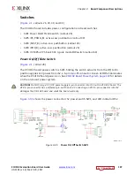
System Reset Pushbuttons
[
, callout 26]
shows the reset circuitry for the processing system.
PS_POR_B Reset
Depressing and then releasing pushbutton SW4 causes net PS_POR_B to strobe Low. This
reset is used to hold the PS in reset until all PS power supplies are at the required voltage
levels. It must be held Low through PS power-up. PS_POR_B should be generated by the
power supply power-good signal. When the voltage at IN1 is below its threshold or EN1
(P.B. switch SW4 is pressed) goes Low, OUT1 (PS_POR_B) goes Low.
PS_SRST_B Reset
Depressing and then releasing pushbutton SW3 causes net PS_SRST_B to strobe Low. This
reset is used to force a system reset. It can be tied or pulled High, and can be High during
the PS supply power ramps. When the voltage at IN2 is below its threshold or EN2 (P.B.
switch SW3 is pressed) goes Low, OUT2 (PS_SRST_B) goes Low.
Active-Low Reset Output RST_B asserts when any of the monitored voltages (IN_) falls
below its respective threshold, any EN_ goes Low, or MR is asserted. RST_B remains asserted
for the reset time-out period after all of the monitored voltages exceed their respective
threshold, all EN_ are High, all OUT_ are high, and MR is de-asserted. See the
Zynq
Ult MPSoC Technical Reference Manual
(UG1085)
for information for
information concerning the resets.
X-Ref Target - Figure 3-43
Figure 3-43:
PS SRST_B and POR_B Pushbutton Switches SW3 and SW4
;


