


24
SP305 Spartan-3 Development Platform User Guide
www.xilinx.com
UG216 (v1.1) March 3, 2006
SP305 Spartan-3 Development Platform User Guide
R
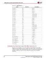
Single-Ended Expansion I/O Connectors
Header J6 contains 32 single-ended signal connections to the FPGA I/Os; thereby
permitting the signals on this connector to carry high-speed single-ended data. All single-
ended signals on connector J6 are matched length traces. The VCCIO of these signals can
be set to 2.5V or 3.3V by setting jumper J29.
Table 2-24
summarizes the single-ended
connections on this expansion I/O connector.
J5, Pin 46
HDR2_46
AA24
J5, Pin 48
AA23
HDR2_48
J5, Pin 50
HDR2_50
W24
J5, Pin 52
W23
HDR2_52
J5, Pin 54
HDR2_54
Y23
J5, Pin 56
Y22
HDR2_56
J5, Pin 58
HDR2_58
Y26
J5, Pin 60
Y25
HDR2_60
J5, Pin 62
HDR2_62
AA26
J5, Pin 64
AA25
HDR2_64
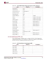
Table 2-23:
Expansion I/O Differential Connections (J5)
(Continued)
Header Pin
(Diff Pair
Neg)
Label
(Diff Pair
Neg)
FPGA Pin
(Diff Pair
Neg)
Header Pin
(Diff Pair
Pos)
FPGA Pin
(Diff Pair
Pos)
Label
(Diff Pair
Pos)
Table 2-24:
Expansion I/O Single-Ended Connections (J6)
Header Pin
Label
FPGA Pin
J6, Pin 2
HDR1_2
R21
J6, Pin 4
HDR1_4
T22
J6, Pin 6
HDR1_6
T23
J6, Pin 8
HDR1_8
V2S
J6, Pin 10
HDR1_10
U23
J6, Pin 12
HDR1_12
R19
J6, Pin 14
HDR1_14
R22
J6, Pin 16
HDR1_16
P25
J6, Pin 18
HDR1_18
U24
J6, Pin 20
HDR1_20
T26
J6, Pin 22
HDR1_22
T25
J6, Pin 24
HDR1_24
R26
J6, Pin 26
HDR1_26
P26
J6, Pin 28
HDR1_28
V24
J6, Pin 30
HDR1_30
R25
J6, Pin 32
HDR1_32
V23
J6, Pin 34
HDR1_34
R20
J6, Pin 36
HDR1_36
V22


