


SP305 Spartan-3 Development Platform User Guide
21
UG216 (v1.1) March 3, 2006
www.xilinx.com
Detailed Description
R
audio with up to 48-kHz sampling. The sampling rate for record and playback can be
different.
Table 2-19
lists the FPGA pins.
Label
FPGA Pin
Description
AUDIO CLOCK
DATA IN
DATA OUT
SYNC
RESET
Note:
The reset for the AC97 codec is shared with the reset signal for the flash memory chips and
is designed to be asserted at power-on or upon system reset.
Separate audio jacks are provided for Microphone, Line In, Line Out, and Headphone. All
jacks are stereo except for Microphone jack. The Headphone jack is driven by the audio
codec's internal 50-mW amplifier.
Table 2-20
summarizes the audio jacks.
Reference
Designator
Function
Stereo/Mono
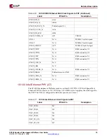
VGA Output (30)
A VGA output port (P2) is present on the board to support an external video monitor. The
VGA circuitry utilizes a 50-MHz, 24-bit color video DAC (Analog Devices
ADV7125KST50).
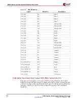
Table 2-21
defines the VGA FPGA pins.
Note:
The VGA connector does not support plug and play protocol via ID0/ID1 pins.
Note:
The VGA connector does support the IIC port where ID1 is connected to IIC_SDA_VGA. NC3
is connected to IIC_SCL_VGA. Both IIC_SDA_VGA and IIC SCL_VGA are connected respectively to
IIC SDA and IIC SCL through a Zero ohm resistors R159 and R160.
Table 2-19:
AC97 FPGA Pin Connections
AUDIO_BIT_CLK
AE13
AUDIO_SDATA_IN
AC13
AUDIO_SDATA_OUT
D2
AUDIO_SYNC
E3
FLASH_AUDIO_RESET_N
AB13
Table 2-20:
SP305 Audio Jacks
J11
Microphone - In
Mono
J12
Analog Line - In
Stereo
J13
Analog Line - Out
Stereo
J14
Headphone - Out
Stereo
Table 2-21:
VGA FPGA Pins
Label
FPGA Pin
Description
VGA_B0
D11
4.7K to GND
VGA_B1
B11
4.7K to GND
VGA_B2
A11
4.7K to GND
VGA_B3
L8
Blue 3


