


SP305 Spartan-3 Development Platform User Guide
9
UG216 (v1.1) March 3, 2006
www.xilinx.com
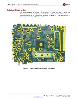
Detailed Description
R
the maximum capable. The SP-305 board is normally shipped with a 15W power supply
which should be sufficient for most applications.
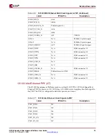
Oscillator Sockets (5)
On the back side, the SP305 Development Platform has two crystal oscillator sockets, each
wired for standard LVTTL-type oscillators. (Note: A 100 MHz oscillator is pre-installed in
the X1 SYSCLK socket.) These connect to the FPGA clock pins as shown in
Table 2-2
. The
oscillator sockets accept half-sized oscillators and are powered by the 3.3V supply.
Label
Clock Name
FPGA Pin
SYSCLK
USERCLK
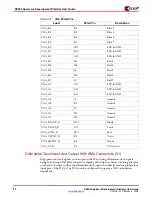
DIP Switches (6)
There are eight general purpose (active-high) DIP switches connected to the user I/O pins
of the FPGA. See
Table 2-3
for a summary of these connections.
SW1
FPGA Pin
SW1
FPGA Pin
Figure 2-4:
Power Supply Diagram
TP
S
54
3
10
3
A
S
WIFT
TP
S
54
3
10
6A
S
WIFT
TP
S
51100
3
A DDR LDO
TP
S
7
3
118
150mA LDO
TP
S
54
3
10
3
A
S
WIFT
5V Brick
3
A
1.25V
to VTT
1.2V
5V
5V to U
S
B
a
nd P
S
/2
2.5V to DDR
S
DRAM
to FPGA Core
3
.
3
V
to FPGA I/O. Digit
a
l
Su
pply
1.8V
to PROM
UG216_04_101105
Table 2-2:
Oscillator Socket Connections
X1
AD13
X6
AE14
Table 2-3:
DIP Switches Connections (SW1)
1
AE8
5
AB9
2
AF8
6
AC9
3
Y9
7
AD9
4
AA9
8
AE9


