Warning
Do not extend the drawer beyond this service position. Pulling the drawer further out
will disengage it from the rails resulting in damage to the drawer and possible injury.
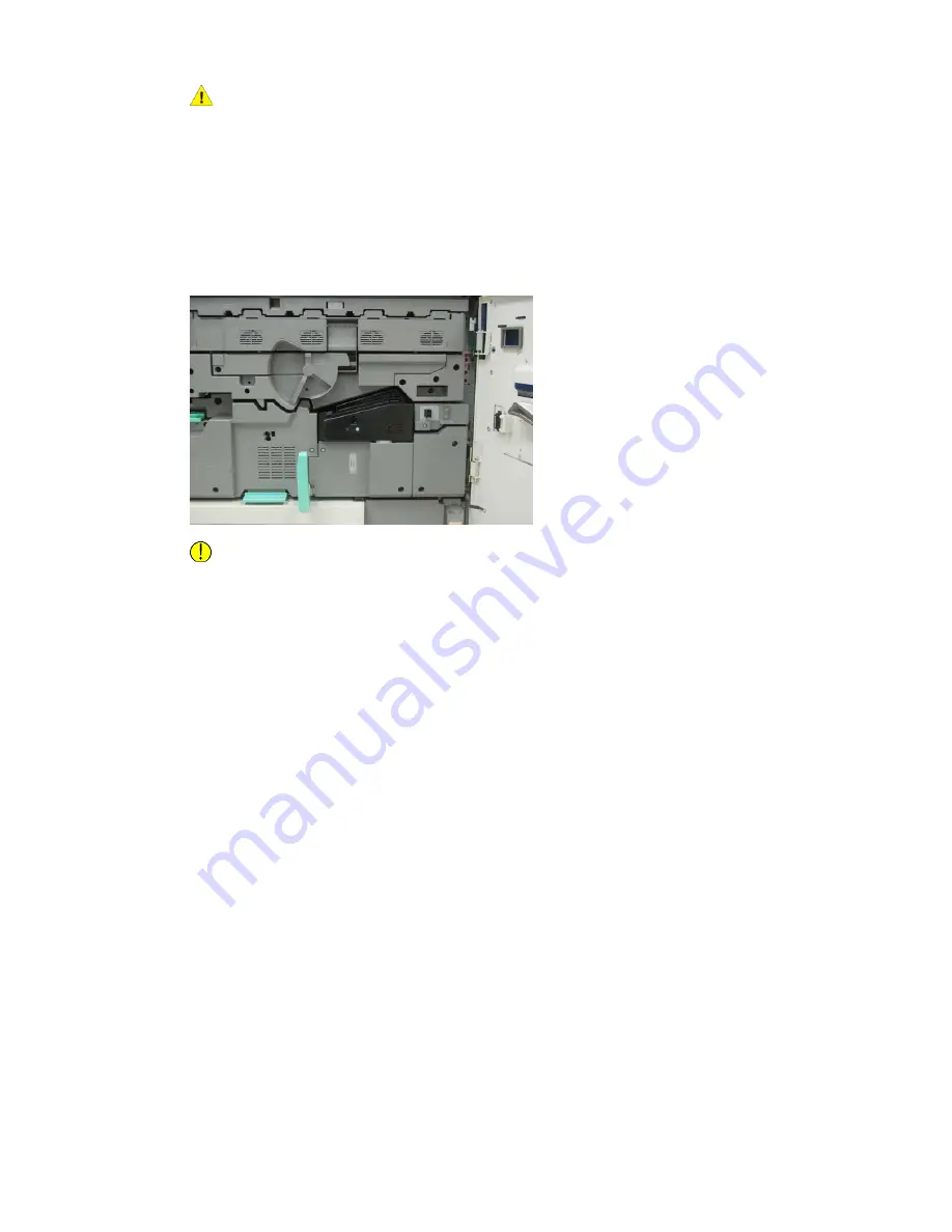
6. Locate the black Fuser Front Cover. Notice if there is a black or gray fuser width
identifier clip at the front left side of the cover. The clip identifies the width of the
fuser currently installed, such as 13 inch. If there is no clip and jumper connected
(this is the default at install), the standard fuser is installed, which accommodates
all paper widths.
7. Using the provided T10 Torx driver, remove one screw and the Fuser Front Cover.
Caution
Save all screws for reinstallation. If you drop a screw inside the Fuser Assembly, make
sure to locate and remove the screw before continuing. Otherwise, the press could
be damaged or an image quality issue or fault code may result.
8. Remove the two mounting screws using the provided T15 Torx driver and lift the
Fuser Top Cover to the access position.
9. If there is a jumper harness attached to the wire bundle, it identifies the fuser width
restriction/resistence. One of two resistence jumpers may be installed. No jumper
(this is the default) indicates that the standard fuser is installed. Disconnect the four
Fuser connectors:
a) Pinch the tabs on both sides of the black connector and lift to remove.
b) Using a Torx driver, gently push the tabs in on each of the three white connectors
while pulling slightly on the wires to remove.
5-23
Xerox
®
Versant™ 2100 Press
Quick Start Guide
Maintenance


