background image

6 Maintenance 

8265/8290/8365/8390 User Guide 

119 

6.3.4.2 Change upper sponge at back of the capping station. 


Step 1 : 

Power ON the printer. 


Step 2 : 

Go to the H.Unlock Menu and press F2. 


Step 3 : 

Open the Front Cover. 


Step 4 : 

Slide the carriage to the left to access the upper sponge. 


Step 5 : 

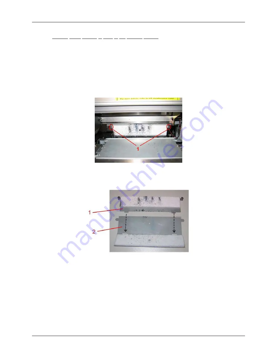
Remove the two screws fixing the sponge (1). 


1 = Screws fixing the sponge (1) 


Step 6 : 

Replace the sponge and tighten it again to the plate with the two screws. 


1 = Capping sponge 
2 = Plate 


Step 7 : 

Close the Front Cover. 


Step 8 : 

Press the [ENTER] key to exit the H.Unlock Menu.  The carriage will cap in and be locked. 


Summary of Contents for 8290

Page 1: ...May 2008 701P48331 8265 8290 8365 8390 Wide Format Color Printer User Guide ...

Page 2: ......

Page 3: ...circumstances shall be used in the manufacture or reproduction of the article shown and the delivery of this document shall not constitute any right or license to do so WEEE regulations Environmental information Disposal of your old product Your product is designed and manufactured with high quality materials and components which can be recycled and reused When this crossed out wheeled bin symbol ...

Page 4: ...This page has been intentionally left blank ...

Page 5: ...2 8 Winder Un winder Operation Labels 17 3 Printer Setup 19 3 1 Turning the Printer Power ON OFF 19 3 1 1 Turning the Power ON 19 3 1 2 Turning the Power OFF 19 3 2 Turning the Winder Un winder Power ON OFF 21 3 3 Connecting the Network Interface 22 3 4 Media Handling 23 3 4 1 Loading Sheet Media 23 3 4 2 Loading Roll Media 25 3 4 3 Setting Media Type 28 3 5 Test Printing 29 3 5 1 Setup List 31 3 ...

Page 6: ...1 5 3 Error Messages 98 5 3 1 Status Messages 98 5 3 2 Error Message Display and Solutions 99 5 3 3 Data Error Display and Solutions 101 5 3 4 Command Error Display and Solutions 101 5 3 5 Error Requiring a Printer Restart 102 5 4 When Media Jams Occur 103 6 Maintenance 105 6 1 Introduction 105 6 2 8265 8290 Periodic Maintenance 105 6 2 1 Weekly Maintenance 106 6 2 2 Bi weekly Maintenance 108 6 2 ...

Page 7: ... 7 2 Starting up after a LongStore 131 7 Adjustments 133 7 1 Uni Directional Adjustment 133 7 2 Bi Directional Adjustment 135 7 3 Step Adjustment 137 7 3 1 Print the Dist Check Test Pattern 137 7 3 2 Evaluate the Dist Check Test Pattern 138 7 3 3 Modify the Step Adjust Printer Setting 139 8 Appendix 141 8 1 Product Specifications 141 8 2 Network Interface Specifications 141 ...

Page 8: ...iv 8265 8290 8365 8390 User Guide This page has been intentionally left blank ...

Page 9: ...rtant information and useful tips on the operation of your printer 1 3 IMPORTANT SAFETY INSTRUCTIONS General safety instructions that must be observed to use the equipment safely are explained below Do not place the printer in the following areas Doing so may result in the printer tipping or falling over and causing injury Unstable surfaces Sloping floors Areas subject to vibration by other equipm...

Page 10: ...o not bend twist or pull the cable Do not wire the cable near equipment that generates heat Follow the instructions below when handling the power plug Otherwise fire may occur Wipe away dust and any other residue before inserting the plug Ensure that the plug is firmly inserted as far as it can go When handling the foot switch be aware of the following Do not place anything heavy on the foot switc...

Page 11: ...ver open the covers fixed with screws except the left cover Doing so may result in electrical shock or a malfunctioning of the printer Do not touch the cutter blade Doing so may result in bodily injury Do not cut hard objects or drop the cutter Doing so may damage or chip the cutter blade Do not bend or pull the waste fluid tube Doing so may cause that the waste fluid will leak out and malfunction...

Page 12: ...ndling the labels Notes Make sure that all labels can be recognized If text or illustrations cannot be seen clearly either clean or replace the label When cleaning labels use a cloth with water or neutral detergent Do not use a solvent or gasoline If a warning label is damaged lost or cannot be recognized replace the label When replacing warning labels contact your local Xerox Customer Service Rep...

Page 13: ...1 Safety Instructions 8265 8290 8365 8390 User Guide 5 No Type 1 2 3 4 5 ...

Page 14: ...1 Safety Instructions 6 8265 8290 8365 8390 User Guide 6 7 8 9 ...

Page 15: ... 7 10 1 4 2 2 Location and Types of Warning Labels on the Rear of the Printer No Type 3 CAUTION THIS UNIT HAS TWO POWER SUPPLY CORDS WHEN WINDING UNIT IS PROVIDED TO REDUCE THE RISK OF ELECTRICAL SHOCK DISCONNECT ALL POWER SUPPLY CORDS BEFORE SERVICING 4 ...

Page 16: ...1 Safety Instructions 8 8265 8290 8365 8390 User Guide This page has been intentionally left blank ...

Page 17: ...up to 1 1 mm 3 Vibrant Colour Reproduction To reproduce sharp and vivid colour either 4 or 6 ink colours are used for printing Ink cassette come in either 220ml or 440ml capacity with an IC chip that tracks the ink quantity in the cassette significantly improving productivity 4 Effective usage of media A media feed feature is provided allowing the user to feed media forward or backward to set the ...

Page 18: ...operating Only open and or close the cover to perform following operations Media setting and replacement Cutter blade replacement Cleaning the cleaning wiper 3 Carriage Drives and holds the print heads 4 Operation panel To control the printer 5 Ink compartment cover Covers the ink compartment 6 Stand Carries the main body 7 Waste bottle assembly Collects the waste fluid 8 Winder Rolls up the roll ...

Page 19: ...0 User Guide 11 2 2 2 Rear of Printer No Connection 1 Ethernet connector 2 Card reader slot 3 SmartChip label 4 Bracket Cover 5 Centronics connector 6 Foot switch connector 7 Power inlet 8 Environmental label 9 DB 25 connector 10 ID label ...

Page 20: ...a coated and uncoated Optimizes the dot gain control Post Fixer Heater C 20 70 C The post fixer finalizes the fixation process and helps to make the prints touch dry Dryer Heater D 20 50 C The dryer completes the drying for compatibility with the take up in combination with higher output speeds Stickiness of printed banner materials is improved For user 1 and user 8 default settings are as follows...

Page 21: ...d to F2 4 F3 key Executes the function assigned to F3 Executes the function assigned to F3 5 F4 key Executes the function assigned to F4 Executes the function assigned to F4 6 MENU key Changes the LCD monitor display to the setup menu status Changes the menu in reverse order 7 MENU key Changes the LCD monitor display to setup menu status Changes the menu in forward order 8 ENTER key Displays the p...

Page 22: ...OFF The printer is waiting to receive print data ON The pressure roller is in the release position Media has not been loaded 14 MEDIA SET lamp Orange OFF The pressure roller is in the secured position The media has not been loaded ON The media type is set to roll media 15 ROLL lamp Orange OFF The media type is set to sheet media ON The media type is set to sheet media 16 SHEET lamp Orange OFF The ...

Page 23: ...ally 3 PCB Box Contains the boards to control the UW W 100 4 Motorized roll unit Supports and winds up the roll media 5 Roll unit bar Supports the roll units 6 Roll unit Supports the roll media 2 2 6 Unwinder Rear No Name Function 1 Rear tensioning system Adjust the tension between the print platform and the unwinding system 2 Roll unit Supports the roll media 3 Motorized roll unit Supports and un...

Page 24: ...hts up when pushing one of the buttons Motor turns LED flashes Motor is off LED is out Motor accelerates LED burns continuously Outside printing Inside printing 4 Backwards button Roll off unwinder Roll up unwinder 5 Forwards button Roll up unwinder Roll off unwinder 6 Winder 100 switch Toggle between Manual 0 and Automatic I mode Manual 7 Winder 100 LED Automatic LED lights up when pushing one of...

Page 25: ...Notes Make sure that all labels can be recognized If text or illustrations are invisible clean the label When cleaning labels use a cloth with water or neutral detergent Do not use a solvent or gasoline If an operation label has been damaged lost or cannot be recognized replace the label Foot switch label Roll unit handle label Front tensioning label Rear tensioning label PCB box label ...

Page 26: ...2 Printer Overview 18 8265 8290 8365 8390 User Guide This page has been intentionally left blank ...

Page 27: ...p operations Step 3 After finishing initial start up operations the unit will enter the normal operating condition Notes If there are any problems during the initial start up operation the unit will display a message on the operation panel and the operation may stop If the operation stops refer to Troubleshooting and take the appropriate actions 3 1 2 Turning the Power OFF Turn the power of the un...

Page 28: ... again while the following message is displayed Step 4 The product will perform the power OFF operation Following message is displayed on the operation panel All lamps and the LCD of the operation panel will turn OFF The product will automatically turn the power OFF after performing a tubing flush Notes If there are problems during the power OFF operation the unit will display a message on the ope...

Page 29: ... THE WINDER UN WINDER POWER ON OFF The switch in located on the power supply box Its status is marked with O and I I Switched ON Power LED on control panel of winding system will light up O Switched OFF Power LED on control panel of winding system will not be lid ...

Page 30: ... electrical shock or fire may occur o Do not touch the connector o Do not connect the network cable connector to the interface board having different specifications Step 1 Turn off the printer Step 2 Plug the connector of the Ethernet cable into the connector of the network interface board at the back of the printer 1 Network interface connector 2 Interface cable Step 3 Connect the other end of th...

Page 31: ...to the printer wind the media up and then load the sheet media Step 1 Turn the printer on Step 2 The printer starts the initialize operation The following message is displayed on the operation panel Notes If you do not want to use the media detection at the media initialization Set to OFF in the media detection setup item Step 3 Verify if the sheet lamp on the operation panel is unlit Step 4 Press...

Page 32: ...rinter 1 Sheet media 2 Insertion slot Step 7 Set the right edge of the media so that it is parallel with the media setting position Notes The media set position is a guideline for setting up the media If the right edge of the sheet media is 5 mm or more from the media setting position a media set error may occur if the media is not detected Make sure to set the right edge of the sheet media within...

Page 33: ...ng the media roll Step 1 Determine the printable side of the media roll inside or outside printing and lay down the media roll as shown in the images below Step 2 Position the roll units of the unwinder in such a way that the media roll can be placed in between 1 Roll unit handle 2 Roll unit 3 Media roll Step 3 Lock one roll unit to the roll unit bar Step 4 Place one side of the roll over the flan...

Page 34: ... of the Unwinder 3 4 2 2 Loading the media into the printer PART 1 INSTALLING AN EMPTY CORE AND LOADING THE MEDIA THROUGH THE REAR TENSIONING SYSTEM Step 1 Make sure the printer and UW W 100 are ON Step 2 Press the F4 key to raise the pressure rollers Step 3 Open the front cover Step 4 Install an empty core between the motorized roll unit and roll unit of the winder unit on front of the printer No...

Page 35: ... middle Step 4 Lower the pressure rollers of the printer Step 5 Set the unwinder REAR unit to AUTOMATIC Step 6 The rear tensioning system will go to its initial position Step 7 Close the front cover Step 8 Start printing until the media reaches the front core of the winder OR feed the media without printing Step 9 Use tape to fix the media end to the empty core installed at the winder unit Start t...

Page 36: ...wing keys on the operation panel and select the current media type When alternating roll sheet media selection F2 When changing from media loading F3 When changing media type F4 Setup items Key Parameters Description Roll media Media type F2 Sheet media Alternates the roll media type Roll media Set when loading roll media Sheet media Set when loading sheet media Lever up Lever Down Up F3 Lever dow...

Page 37: ...out doing anything Step 4 When the media initial operation finishes the printer moves to normal status The setting media loading procedure has been completed 3 5 TEST PRINTING Follow the steps below to do a test print and confirm if your printer operates correctly Step 1 Turn the power of the unit ON and load the media Step 2 Make sure that your printer is in normal status Step 3 Press either the ...

Page 38: ...Refer to Nozzle Check F3 Adj Uni D Perform the Uni Directional Alighment Refer to Adjustments Test Print 1 2 F4 Adj Bi D Perform the Bi Directional Alignment Refer to Adjustments F1 Palette Perform Colour Palette Refer to Colour Palette Test Print 2 2 F2 Maintenance Perform Maintenance record Refer to Maintenance record Step 6 Print the information on the selected item Step 7 After printing the pr...

Page 39: ...3 Printer Setup 8265 8290 8365 8390 User Guide 31 3 5 1 Setup List Use this function to check the current status of the printer ...

Page 40: ...y clogging of nozzles missing dots or faint printing Notes If printing quality declines or if missing dots are evident after the NozzleCheck the print heads need to be cleaned Refer to Head cleaning to perform head cleaning After finishing the head cleaning wait for 10 minutes and perform the NozzleCheck again ...

Page 41: ...de 33 3 5 3 Colour Palette Use this function to compare the colour settings of the computer print colour of the printer This palette is printed in the mode you are currently working PrintMode settings We recommend printing the palette in 360x360 ...

Page 42: ... 8365 8390 User Guide 3 5 4 Maintenance Record Use this function to check the life cycles of the printer parts Notes A part s life cycle is shown by the amount of the mark When a part s life cycle comes to an end the mark reduces ...

Page 43: ... 4th line Displays the currently set media type 7 Right of 4th line Displays the approximate amount of remaining media that is currently set Units m However the amount is displayed only when either Roll media 1 Roll media 2 or Roll media 3 is selected in the Roll media setting menu 4 1 2 Setting Menu Display In the SetupMenu changes can be made to the printer settings The content displayed on the ...

Page 44: ... the Setting menu display Notes Refer to Setup menu for details of the setting menu 4 1 3 2 Changing the status from the setting menu display to normal Take one of the following actions when the printer is in the setting menu display to change the operation panel display to normal one Press the CANCEL key on the operation panel Leave the printer for 3 minutes when the status is in the setting menu...

Page 45: ...ia in an appropriate environment Following are the appropriate temperature and humidity ranges for printing Temperature Humidity Recommended working environment 74 F 23 C 40 to 70 Rate of change Within 36 F 2 C per hour Within 5 per hour Do not use creased damaged torn curled or wrapped media The size of the recommended sheets can change at a fixed ratio according to the temperature changes of the...

Page 46: ...o not store media in high temperature high humidity or direct sunlight Store sheet media in the original bag after unpacking Unused roll media must be removed from the scroller rewound tightly and stored in the original wrapping bag and the box Do not wet media 4 2 4 Media Printing Area The printing area is shown below 1 Roll media 2 Sheet media ...

Page 47: ...tion describes how to set the Menu settings on the operation panel and setup items Follow the steps below to set the Menu settings Step 1 Make sure that the operation panel is normal Step 2 Press the MENU or MENU key I The screen shows following Menu SetupMenu VersionCheck Area 7 7 ...

Page 48: ...ing Sets Centronics Interface communication mode SetupMenu 3 7 Network setting Makes the settings for the network interface Utility setting Makes various advanced function settings File management setting Makes various settings for the processing method of the printing data sent from computer to the installed hard disk in the printer SetupMenu 4 7 Initialize setting Returns the parameters to facto...

Page 49: ... slots 7 8 Symbols Parameter 1 Parameter 2 Parameter 3 Param 1 Ink Colour Values K Black C Cyan M Magenta Y Yellow c Light Cyan m Light Magenta W Cleaning Liquid Param 2 Ink Remaining Values 25 Ink status for the ink cassette slots 1 8 Mode Indicated on the lower right corner Values UltraE Eco Solvent 8265 8290 MS Mild Solvent 8365 8390 InkStatus CANCEL key shifts to the previous menu Refer to Set...

Page 50: ...rint head position and media feed amount by operating the following keys F1 key Feeds media forward F2 key Moves the print head to the left F3 key Feeds media backward F4 key Moves the print head to the right ENTER key Determines the setup values then returns to the previous hierarchical menu OriginSet CANCEL key shifts to the previous hierarchy menu Refer to Setup menu Notes When printing data fr...

Page 51: ...Adjustment 8 1 TestPrint 1 2 2 2 CANCEL key shift to the previous hierarchy menu 4 3 1 4 MediaSet Menu Setup items Parameters Description Media Sets the media type used for test printing SheetSize To set the method for detecting the size of the media when sheet media has been loaded Topfeed Sets the amount of media to be fed when printing begins Make this setting when using roll media Mediacut The...

Page 52: ...Description User media 1 User media 2 User media 3 Media 1 2 User media 4 User media 5 User media 6 User media 7 Media 2 2 User media 8 To set the type of media used for printing For setup values of printing operation eight settings of user media 1 8 can be set Media 1 2 2 2 CANCEL key to shift to the previous hierarchy menu ...

Page 53: ...XEROX dealer Setup items Parameters Description InkDryTime In order to let the ink for the printing dry the time between the end of the print and the beginning of the next print is set H Height Sets the distance head height between the print head and the media Stiffness Makes the setting on the stiffness of the media to be used User 1 8 1 3 Thickness Makes the setting on the thickness of the media...

Page 54: ...Set the distance head height between the print head and the media Head height can be changed to three levels according to media thickness Setup items Parameters Description low When using media with a thickness of 80µm to 300µm middle When using media with a thickness of 300µm to 700µm Hhgh When using media with a thickness of 700µm to 1000µm HeadHeight 1 µm 0 001 mm Notes Set the height of the he...

Page 55: ...n Thickness 50µm 100µm 1500µm Change media thickness by operating the following keys F2 key to increase the setup value F4 key to decrease the setup value ENTER key to confirm the setup value CANCEL key to cancel the setup value Notes Bidirectional quality can only be obtained when media thickness is set correctly 4 3 1 11 Heater A Menu Set the temperature of the Heater Setup items Parameters Desc...

Page 56: ...ange fixer temperature by operating the following keys F2 key to increase the setup value F4 key to decrease the setup value ENTER key to confirm the setup value CANCEL key to cancel the setup value 4 3 1 13 Post Fixer C Menu Set the temperature of the Post Fixer Setup items Parameters Description Post Fixer C OFF 50 C Change post fixer temperature by operating the following keys F2 key to increas...

Page 57: ... ENTER key to confirm the setup value CANCEL key to cancel the setup value Notes The default setting for the drier is set to 50 C The function of the drier D Heating the printed transfer paper evaporates the water fast enough so that the print is touch dry when wound 4 3 1 15 HStatus Menu Check the temperature of the heating elements Notes A stands for the Heater B stands for the Fixer C stands fo...

Page 58: ... value The menu changes to the Change Media Feed Correction Value menu Print2 Performs printing by media feed compensation for fine adjustment A correction pattern with a width of 0 02 in steps of 0 01 is printed around the centre of the correction value currently set Dist Adj CANCEL key Shifts to the previous hierarchy menu 4 3 1 17 Change menu Change the distance adjustment value Setup items Par...

Page 59: ...enu When loading a sheet of media set the method for detecting the size of the media Setup items Parameters Description Auto The length and width of the sheet media is automatically detected Length When placing normal size sheet media vertically on the tray Width When placing normal size sheet media horizontally on the tray SheetSize After setting shift to the previous hierarchy menu Notes When us...

Page 60: ... automatically cut Manual Feed media to the media cut position after printing Use regular cutting blades available from hardware stores Off No media feed after printing Media cutting When Auto is selected proceed to the Shortest Cut Length menu If Manual or Off has been selected the screen changes to the menu of the previous hierarchy Notes For the situations shown below the media cut settings are...

Page 61: ... 4 3 2 2 PrnMode Menu Perform various settings for Print mode For each setup value of Print mode four settings of Printing mode 1 Printing mode 4 can be set Setup items Parameters Description Printing condition To set printing quality Printing direction To set print head moving direction for printing Repeat printing To make settings for the repeat print PrnMode 1 4 1 2 Head speed To set the head s...

Page 62: ...0dpi Condition 3 5 2160x1080dpi 1080x2160dpi Diag2160dpi 2880x1440dpi Condition 4 5 1440x2880dpi Condition 5 5 Diag2880dpi The display changes to interlace setup items after the print quality items settings have been finished Condition 1 5 5 5 CANCEL key To shift to the previous hierarchy menu Condition 540x720 720x720 1080x1080 1440x720 360x360 2 5 Condition 720x1440 Diag1440 1440x1440 2160x1080 ...

Page 63: ...rint Setup items Parameters Description Count To set the number of repeats per line of printing IntervalTime To set interval time for the repeat print RepeatPrn CANCEL key To shift to the previous hierarchy menu 4 3 2 6 Count Menu Set the number of repeats per line of printing Setup items Parameters Description Count Once to 99 times To change repeat times by operating the following keys F2 key to...

Page 64: ...ating the following keys F2 key to increase the setup value F4 key to decrease the setup value ENTER key to confirm the setup value CANCEL key to cancel the setup value 4 3 2 8 HeadSpeed Menu Only applicable when printing in 360dpi Setup items Parameters Description Normal Print at normal speed of 360 dpi Fine Print at the speed of 720 dpi slower more drying time HeadSpeed CANCEL key To shift to t...

Page 65: ...at will save you time and boost your output quality Difficult images will print smoother banding will be suppressed neutralized and you will have to spend less time fine tuning your printer to create great looking output Moreover when using wave tuned profiles you will be able to boost your printer s colour gamut as the i intelligent interweaving technology allows depositing more ink helping you t...

Page 66: ...eferred setting for non sign images pictures continuous tone data no speed loss 4 pass is a quality mode and will always use a tuned sign weave pattern even if picture is selected from the panel RIP 2 pass 720x720 4 pass 2 pass 540x720 4 pass Stitch Creates a fine print swath overlap Mildly improves print quality versus Off setting lowest level of interweaving 4 pass data will be printed as classi...

Page 67: ...h Carriage moves over the media Depending on MediaWidth ScanWidth FullWidth Carriage moves over the full width Long 4 3 2 11 Command Menu Perform various settings for printer commands Setup items Parameters Description Step To set the units for amount of movement for printing Resolu Makes settings for image resolution while printing with image data Command 1 2 OnlineTimer Makes settings for the ti...

Page 68: ...lease note that some software packages use the step per mm terminology in which case a program step of 0 025 mm corresponds with 40 steps per mm and a program step of 0 010 mm with 100 steps per mm 4 3 2 13 Resolu Mmenu Set resolution for image data for printing Setup items Parameters Description 360dpi 600dpi 720dpi Resolu 1 2 1080dpi 1200dpi 1440dpi 2160dpi Resolu 2 2 2880dpi Makes settings for ...

Page 69: ... 3 2 15 Layout Menu Make various settings on layout function Notes The layout function automatically determines the size of printing data sent from the computer and then determines the amount of roll media required without wasting media If sheet media has been loaded the layout function is disabled Setup items Parameters Description Joint Makes settings for stitching print CtPos To set the media c...

Page 70: ...r processing of printing data Setup items Parameters Description CMYÆK Makes settings for printing method to present black Scale Sets the enlargement and reduction ratios for printing data Mirror To draw reversed printing data Function CANCEL key Shifts to the previous hierarchy menu 4 3 2 19 CMY Æ K Menu Replace CMY values with K black Setup items Parameters Description No If MH GL GL2 are set on...

Page 71: ...Menu Perform various settings for roll media Setup items Parameters Description Disable Set this when roll media setup is not used Roll1 Roll2 Roll3 For each setup value of roll media 3 settings of Roll media 1 Roll media 3 can be set RollSetup CANCEL key To shift to the previous hierarchy menu ...

Page 72: ...ing keys F2 key to increase the setup value F4 key to decrease the setup value ENTER key to confirm the setup value CANCEL key to cancel the setup value 4 3 3 3 Centro Menu Set communication mode to Centronics interface Setup items Parameters Description Centro To set communication mode to Centronics mode Bi Centro To set communication mode to Bi Centronics mode Centro To shift to the previous hie...

Page 73: ...sk To set the subnet mask of the product Network 1 1 Gateway To set the IP address of the connected gateway Network CANCEL key To shift to the previous hierarchy menu 4 3 3 5 IPaddress Menu Set the IP address of the product Setup items Parameters Description IPaddress 000 000 000 000 223 255 255 254 Use the following keys to change the IP address F1 key Moves one digit to the left on the setting v...

Page 74: ...e setting value and moves the screen to the menu of the previous hierarchy CANCEL key Cancels the setting value and moves the screen to the menu of the previous hierarchy Refer to Network setting menu 4 3 3 7 Gateway Menu The product sets the IP address of the connected gateway Setup items Parameters Description Gateway 000 000 000 000 223 255 255 254 Use the following keys to change the IP addres...

Page 75: ...ormed for initial media to set the width of the media in the tray Prn Wipe To wipe while printing to take care of possible condensation on the print head nozzle plate SmartTop The ideal temperature of the media is near to the preheater This area of paper is fed before a print starts to obtain perfect quality AutoClean Performs cleaning cycle while printer is idle at the set temperature Utility 2 3...

Page 76: ...hen using the winding system and media is most right loaded RollFeed Should be selected when using the winding system and media is centre loaded PaperDet CANCEL key to shift to the previous hierarchy menu Notes The default setting is RollFeed as a result of the standard unwinder winder 100 with your unit When setting Take up Mechanism on the Media Detection menu the following limits are applied to...

Page 77: ... the media is set here It can be set in the following ranges 90 model 210mm 2240mm Notes On the media width menu If a value larger than the width of the media has been set media or the product may be contaminated by the ink during printing If a value smaller than the width of the set media has been set media may not be cut correctly Setup items Parameters Description MediaWidth 210mm 841mm 2240mm ...

Page 78: ...inting on media which is pre heated This function will only be visible when the B heater is activated Setup items Parameters Description Off No media feed of 5 centimetres SmartTop ON A media feed of 5 centimetres CANCEL key to shift to the previous hierarchy menu 4 3 4 8 AutoClean Menu Printer performs an automatic cleaning before or during printing Or during an idle period of 1 hour of more Setu...

Page 79: ...ormed CANCEL key To shift to the previous hierarchy menu 4 3 4 10 SlantCh Menu To enable or disable whether the printer performs a slant check after every print of at least 1 meter Setup items Parameters Description Off No SlantCheck SlantCh On Perform SlantCheck CANCEL key To shift to the previous hierarchy menu 4 3 4 11 RemPanel Menu Enables or disables using Remote Panel software Setup items Pa...

Page 80: ...ction Returns parameters in the function setup menu to the factory setting RollSetup Returns parameters in the roll media setup menu to the factory setting Initial 2 3 Centro Returns parameters in the Centronics setup menu to the factory setting Network Returns parameters in the network setup menu to the factory setting Initial 3 3 Utility Returns parameters in the utility setup menu to the factor...

Page 81: ...enu 4 3 4 15 PrintMode Menu Setup values of Printing mode menu are set to the factory default settings Setup items Parameters Description NO No initialization OK To perform initialization PrintMode After setting to shift to the previous hierarchy menu 4 3 4 16 Command Menu Setup values of Command Setup menu are set to the factory default settings Setup items Parameters Description NO No initializa...

Page 82: ...4 3 4 18 Function Menu Setup values of Function setup menu are set to the factory default settings Setup items Parameters Description NO No initialization OK To perform initialization Function After setting to shift to the previous hierarchy menu 4 3 4 19 RollSetup Menu Setup values of Roll Media setup menu are set to the factory default settings Setup items Parameters Description NO No initializa...

Page 83: ...rchy menu 4 3 4 21 Network Menu Setup values of Network menu are set to the factory default settings Setup items Parameters Description NO No initialization OK To perform initialization Network After setting to shift to the previous hierarchy menu 4 3 4 22 Utility Menu Setup values of Utility menu are set to the factory default settings Setup items Parameters Description NO No initialization OK To...

Page 84: ... DataDump CANCEL key To exit Dump Mode To shift to the previous hierarchy menu 4 3 5 2 InkManager Menu Setup items Parameters Description Head Wash To perform a head cleaning Ink Load To load ink InkManager 1 2 Ink Change To change ink configuration 2x4 1x6 LongStore To store your printer for a long time 8365 8390 Only InkSupply To switch between the Bulk Ink System for 8365 8390 and ink cassettes...

Page 85: ... The process consists of several cleaning loadings several air loadings and one ink loading On the display of the operation panel a time indication is mentioned on the fourth line Message Time 1 Please remove cart 2 Ink Discharge 7 3 Please insert Cleaning cart 4 During washing wait for a while 29 5 Remove cassettes 6 During washing wait for a while 7 7 The end 8 Ink Load 13 4 3 5 4 InkLoad Menu S...

Page 86: ... of ink and cleaning liquid it is recommended to change ink types by using the Ink Change cycle The process consists of several cleaning loadings several air loadings and one ink loading On the display of the operation panel a time indication is mentioned on the fourth line Message Time 1 Please remove cart 2 Ink Discharge 1 3 Please insert Cleaning cart 4 During washing wait for a while 5 5 Remov...

Page 87: ...display of the operation panel a time indication is mentioned on the fourth line Message Time 1 Please remove cart 2 Ink Discharge 3 Please insert Cleaning cart 4 During washing wait for a while 5 Ink not filled ALL 6 Power OFF 29 Notes When a cleaning cassettes is empty during LongStore procedure remove the empty one and replace it by a new one Only the last cycle will be repeated Although the fu...

Page 88: ...e Bulk Ink System to know how to install and use it Setup items Parameters Description Off Using ink cassettes On Using the Bulk Ink System InkSupply CANCEL key shifts to the previous menu 4 3 5 8 ChipMgr menu Setup items Parameters Description Cassette Use the smart chips on the ink cassettes Printer Use the smart chip manager system on the top or back of the machine Recommended when working with...

Page 89: ...hierarchy menu 4 3 6 2 WiperClean Menu Clean the wipers Notes Refer to Cleaning the cleaning wiper for details regarding the procedure for cleaning the cleaning wiper Setup items Parameters Description No Do not clean the cleaning wiper Yes To clean the cleaning wiper WiperClean CANCEL key shifts to the previous hierarchy menu H Unlock No Yes 1 1 H Unlock To lock heads press ENTER WiperClean No Ye...

Page 90: ...ing Notes The tubing flush sequence will not remove fluids out of the head nor out of the ink supply tubes Please refer to the Periodical Services for the daily and weekly maintenance of the 8265 8290 8365 8390 The tubing flush feature includes following sequence 1 The head is moved away from the capping position 2 Pump sequence is started 3 Pumps are stopped and head is re capped The tubing flush...

Page 91: ...stem version Setup items Parameters Description Version Check CANCEL key shift to the previous hierarchy menu 4 3 7 2 Area Menu View the total area of media printed on the machine Setup items Parameters Description Area Total Total area of media CANCEL key shift to the previous hierarchy menu SetupMenu VersionCheck Area 7 7 Area Total 46 16m2 ...

Page 92: ...owing regarding the condition of the printer I It is not currently printing Step 2 Press the F1 key of the operation panel I To shift to the feed reel menu Step 3 Press the F2 key of the operation panel I To shift to the Dist Adj menu Setup items Parameters Description Change Dist Adj 90 00 110 00 Change the distance adjustment value by operating the following keys F2 key to increase the setup val...

Page 93: ...is not currently printing Step 2 Press the F3 key of the operation panel I To shift to the heater menu The heater message can be one of the following o Heater standby o Heater warming up o Heater ready A stands for the heater B stands for the fixer C stands for the post fixer D stands for the dryer S stands for the Set temperature requested temperature R stands for the Real temperature actual temp...

Page 94: ...perature change Press the CANCEL key to leave the menu without changing the heater settings 4 4 2 4 Change the dryer temperature To change the temperature of the dryers press the F4 key on the operation panel The display will mention the following Press the F2 key to decrease the temperature Press the F4 key to increase the temperature Press the ENTER key to confirm the requested temperature chang...

Page 95: ... will turn on orange The pressure rollers have been raised The MEDIA SET lamp turns on orange The pressure rollers are lowered The MEDIA SET lamp will turn off Notes You can also switch the up and down movement of the pressure rollers using the foot switch instead of the operation panel 4 4 4 Print Mode Check Use the following procedure to check the print mode currently set Step 1 Press the ENTER ...

Page 96: ...e requested temperature Step 1 Press the F3 key to ENTER the HeaterStatus menu Step 2 Go to submenu 2 2 and press the F2 key to start the print 4 5 2 Heaters are Ready during Printing When heaters are ready the printer will start printing While printing some actions can be taken 1 On the fly step adjustments In case of overlapped printing images or white lines on printing image the step should be ...

Page 97: ...one Step 1 Press the F2 key of the operation panel I To shift to the cleaning menu Step 2 Press the F1 key or the F2 key on the operation panel I The product will perform following operations Setup items Key name Parameters Description F1 ALL Head 1 Head 2 Clean ALL heads or head couple one or two Cut Feed F2 Little normal powerful Set the intensity of a cleaning Step 3 Press the ENTER key to star...

Page 98: ...esired position When roll media has been set If OFF is set on the cut media menu If Take Up Roll has been set in the media detection setup menu When sheet media has been set Step 1 Make sure that the MEDIA SET lamp on the operation panel is off Step 2 Press the F1 key on the operation panel Step 3 Press the F3 key on the operation panel to feed media to the desired position according to the proced...

Page 99: ... not plug the power cable in Plug in the power cable 2 The front cover is open Close the front cover Refer to Media handling 2 The printer does not work after media has been loaded No Possible cause Solutions References 1 The front cover is open Close the front cover Refer to Media handling 2 The pressure rollers have been raised Lower the pressure rollers lever Refer to Media handling 3 You did n...

Page 100: ...y with media other than recommended media No Possible cause Solutions References 1 The media is damped 2 You used folded creased or curled media Replace with new media Refer to Replacing media 3 Check the media for curling or lift off Use the recommended media When using media other than recommended media set the following items in the media setting menu Media HeadHeight Stiff Refer to Media type ...

Page 101: ...When using media other than recommended media set the following items in the media setting menu Media HeadHeight Stiff Refer to Media type Refer to Menu Overview 8 Roll media cannot be cut correctly No Possible cause Solutions References 1 The edge of the cutting blade is not sharp Replace the cutting blade Refer to Replacing the cutting blade 2 The roll media has static electricity Remove the sta...

Page 102: ...essure rollers Refer to Cleaning the inside of the printer 4 You used the printer in direct sunlight or other locations not appropriate for the specified environment Use the printer in the specified environment Refer to Product Specifications 5 You loaded sheet media into the printer Set the CutSize setting to Length or Width Refer to Menu Overview 6 You used folded creased or curled media Replace...

Page 103: ...edia folded creased damaged tore curled Replace the media Refer to Cautions on handling media 12 Tracing media or other thin media cannot be detected No Possible cause Solutions References 1 You did not use recommended media Use recommended media Refer to Media type 2 You used the printer in direct sunlight or other locations not appropriate for the specified environment Use the printer in the spe...

Page 104: ...at is currently set does not match the command of a computer or a driver Match the command setting of the printer to the environment of a computer or a driver Refer to Menu Overview 16 The printed lines are blurred No Possible cause Solutions References 1 You did not use recommended media Use recommended media Refer to Media type 2 You used too thick or too thin media Use recommended media Refer t...

Page 105: ...e recommended media Use recommended media Refer to Media type 3 Did you try minor adjustments for image quality Try minor adjustments for image quality Refer to Adjustments 19 Bubbles near the Heaters No Possible cause Solutions References 1 You did not use recommended media Use recommended media Refer to Media type 2 You did not set the correct heater Lower the temperature or turn off the Heater ...

Page 106: ...nces 1 Ready to print Waiting for the next operation Media has been loaded 2 Media End The printer is waiting for the next operation No media has been loaded into the printer Refer to Media handling 3 Receiving The printer is receiving data 4 Converting The printer is converting data 5 Printing The printer is printing 6 Warning Waste Ink Tank Replace the waste liquid tank Refer to Replacing the wa...

Page 107: ... occurs while operating the printer When one of the following message type error displays appears the printer may stop operation If the printer stops operation solve the problem to delete the error message and restart the printer 1 Error messages regarding media feeding The following error message is displayed on the first line of the operation panel No Display Descriptions Solutions References 1 ...

Page 108: ...ptions Solutions References 1 Ink Status Cassette Ink cassette s is are empty The printer stops Replace the ink cassette s Refer to Replacing ink cassettes 2 Ink Status No Filled Initial filling has not been performed Perform initial filling of the ink Refer to Installing ink cassettes 3 No original ink You did not load XEROX s recommended ink cassette The printer stops SmartChip is not well posit...

Page 109: ...rs indicating what kind of error occurred 5 3 4 Command Error Display and Solutions Following are command error descriptions and possible solutions during printer operations Command errors are displayed when an error has occurred while converting the command data sent from computer to printer If a command error occurs the following error messages are displayed and the printer stops Solve the probl...

Page 110: ...n the operation panel Press any key on the operation panel to stop the beep sounds If an error requiring a restart has occurred solve the problems to restart the printer and delete the error If the same error message is displayed again contact your local XEROX dealer Be sure to inquire the code numbers of the error messages No Message Descriptions Solutions References 1 E System error An error whi...

Page 111: ...pressure rollers you can use the foot switch instead of the operation panel Step 2 If a piece of media or media dust is stocked in the printer open the front cover and remove the piece of media or media dust Caution Be sure not to pinch your fingers while opening and closing media cover 1 Front Cover Step 3 If there is an error requiring a restart power the printer OFF and ON again Step 4 Go to Me...

Page 112: ...5 Troubleshooting 104 8265 8290 8365 8390 User Guide This page has been intentionally left blank ...

Page 113: ... area around the caps Weekly 2 Cleaning around the bottom of the heads Weekly 3 Cleaning the wipers Bi weekly 4 Replacing the wipers Monthly 5 Replacing the sponge in the spitting box Monthly 6 Change the upper sponge at the back of the capping station Semi Annual Notes All cleaning in Ink areas must be done with Xerox 8265 8290 cleaning solution Above maintenance cycle is based on use 8 hours day...

Page 114: ...o perform the daily maintenance afterwards 6 2 1 1 Cleaning the edge of the cap and the area around the caps Step 1 Power ON the printer Step 2 Go to the H Unlock Menu and press F2 Step 3 Open the Front Cover Step 4 Slide the carriage to the left to access the capping station Step 5 Clean the edges of the caps with the cleaning swab Step 6 Clean the area around the caps with a poly knit wiper If y...

Page 115: ...carriage Step 4 Open the Front Cover Step 5 Slide the carriage into the left maintenance area Step 6 Clean the edges of the heads with a cleaning swab wetted by Eco solvent Cleaning Liquid Make sure you do not touch clean the nozzle plate this would lead to poorer print quality Caution Make sure not to touch the nozzle plate This could lead to poorer print quality It is recommended to wear gloves ...

Page 116: ...2 2 1 Cleaning the wipers Step 1 Power ON the printer Step 2 Go to the WiperClean Menu and press F2 Step 3 Open the Front Cover Step 4 Clean the wipers 4 with a poly knit wiper Use some Eco solvent cleaning liquid to remove drops of ink Caution It is recommended to wear gloves Step 5 Close the Front Cover Step 6 Press the ENTER key to exit the Wiper Clean Menu The carriage will cap in and be locke...

Page 117: ... of tweezers Be sure to insert the wiper correctly as shown below When standing in front of the machine Be sure that the wiper clicks in the wiper holder Step 7 Close the Front Cover Step 8 Press the ENTER key to exit the Wiper Clean Menu The carriage will cap in and be locked Notes Be careful not to break the lips of the wiper arm while installing the wipers Do not touch the wipers with your bare...

Page 118: ...Slide the carriage to the left to access the flushing sponge Step 5 Remove the old flushing sponge with tweezers See image below 1 Sponge 2 Tweezers 3 Gloves Step 6 Install the new flushing sponge in the flushing box Notes Make sure that the 2 holes are on the right side of the flushing box and that the pins of the black box are in the holes of the absorbent 1 Two holes 2 Pin of black box Step 7 C...

Page 119: ...ress F2 Step 3 Open the Front Cover Step 4 Slide the carriage to the left to access the upper sponge Step 5 Remove the two screws fixing the sponge 1 1 Screws fixing the sponge 1 Step 6 Replace the sponge and tighten it again to the plate with the two screws 1 Capping sponge 2 Plate Step 7 Close the Front Cover Step 8 Press the ENTER key to exit the H Unlock Menu The carriage will cap in and be lo...

Page 120: ...ekly maintenance 6 Replacing the sponge in the spitting box Bi weekly maintenance 7 Replacing the wipers 8 Replacing upper sponge at back of the capping station Monthly maintenance Notes All cleaning in Ink areas must be done with Xerox 8365 8390 cleaning solution Above maintenance cycle is based on use 8 hours day 5 days week and 44 weeks year If machine is used more maintenance periods will come...

Page 121: ...box you will find a Good Shape Kit to perform the daily maintenance Normally this is enough for 6 months In case you re out of stock you can order a new kit at Xerox Order Entry Department Go to the consumables list on the Customer Documentation CD for the product code of the good shape kit 6 3 1 1 Cleaning the wipers Step 1 Power ON the printer Step 2 Go to the WiperClean Menu and press F2 Step 3...

Page 122: ...of the mousse in the cap does not change anymore 1 Pipette 2 Caps Step 5 Close the Front Cover Step 6 To stop the tubing flush cycle press enter 6 3 1 3 Cleaning the edge of the cap Step 1 Power ON the printer Step 2 Go to the H Unlock Menu and press F2 Step 3 Open the Front Cover Step 4 Slide the carriage to the left to access the capping station Step 5 Clean the edges of the caps with the cleani...

Page 123: ...k Menu and press F2 Step 3 Open the Front Cover Step 4 Slide the carriage to the left to access the capping station Step 5 Clean the area around the caps with a poly knit wiper If you see ink dust or some thing else clean it immediately so it can not influence the print quality Step 6 Close the Front Cover Step 7 Press the ENTER key to exit the H Unlock Menu The carriage will cap in and be locked ...

Page 124: ...vent Cleaning Liquid Make sure you do not touch clean the nozzle plate this would lead to poorer print quality Caution Make sure not to touch the nozzle plate This could lead to poorer print quality It is recommended to wear gloves 2 as shown on the picture below 1 Cleaning Swabs 2 Gloves Step 7 Close the Front Cover Step 8 Press the ENTER key to exit the H Unlock Menu The carriage will cap in and...

Page 125: ...ont Cover Step 4 Slide the carriage to the left to access the flushing sponge Step 5 Remove the old flushing sponge with tweezers See image below 1 Sponge 2 Tweezers 3 Gloves Step 6 Install the new flushing sponge in the flushing box Notes Make sure that the 2 holes are on the right side of the flushing box and that the pins of the black box are in the holes of the absorbent 1 Two holes 2 Pin of b...

Page 126: ... of tweezers Be sure to insert the wiper correctly as shown below When standing in front of the machine Be sure that the wiper clicks in the wiper holder Step 7 Close the Front Cover Step 8 Press the ENTER key to exit the Wiper Clean Menu The carriage will cap in and be locked Notes Be careful not to break the lips of the wiper arm while installing the wipers Do not touch the wipers with your bare...

Page 127: ...Open the Front Cover Step 4 Slide the carriage to the left to access the upper sponge Step 5 Remove the two screws fixing the sponge 1 1 Screws fixing the sponge 1 Step 6 Replace the sponge and tighten it again to the plate with the two screws 1 Capping sponge 2 Plate Step 7 Close the Front Cover Step 8 Press the ENTER key to exit the H Unlock Menu The carriage will cap in and be locked ...

Page 128: ...ease on Y motor belt when needed 9 Apply grease on roller path carriage when needed 10 Apply grease on capping station camm gears when needed 11 Dust removal in fan area underneath print platform Month Maintenance Action 1 2 3 4 5 6 7 8 9 10 11 12 1 x x 2 x x 3 x x 4 x x 5 x 6 x 7 x x 8 x x 9 x x 10 x x 11 x x Notes All cleaning in Ink areas must be done with Xerox cleaning solution Above maintena...

Page 129: ...w ink cassettes before they are totally empty b The ink cassette becomes empty o The following message is displayed on the operation panel o Printing operation stops o Replace with a new ink cassette as soon as possible Notes When the ink runs out or is low the ink colour is indicated as follows 1 8 The number of the ink cassette slot Refer to Installing ink cassettes All All inks 2 Types Notes Fo...

Page 130: ...quid Notes Do not disassemble ink cassettes Disassembled ink cassettes cannot be used Step 1 If the printer is turned on make sure of the following I Printing or other operations are not performed II Make sure that the display on the operation panel shows the normal state III The MEDIA SET light on the operation panel goes off Step 2 Open the ink compartment cover Caution Be sure not to pinch your...

Page 131: ... print correctly Use up ink cassettes within two years from the date printed on the cassette packages Replace ink cassettes if after six months since installation Step 5 Gently shake the ink cassette the install the ink cassette in the slot Step 6 Close the cover of the ink compartment 1 Ink Compartment Step 7 Make sure that the display on the operation panel returns to normal status Notes If you ...

Page 132: ... the display on the operation panel shows the Ready to Print III The MEDIA SET light on the operation panel is OFF Step 2 Go to H Unlock Menu and press F2 Step 3 Open the front cover Notes Replace the cutting blade as quickly as possible If you leave the carriage at the cutting blade replacement position the head may be clogged with ink Step 4 Slide the carriage to the middle of the platen Step 5 ...

Page 133: ...rial Doing so may damage or break the cutting blade Dispose the used cutting blade put it in a plastic bag in accordance with local regulations or laws Step 7 Insert the new cutter into the media cutting blade holder Step 8 While slightly pressing the cutting blade holder tab return the cutting blade lever to its original position Step 9 Close the front cover Step 10 Press the ENTER key on the ope...

Page 134: ... the power of the printer is ON I Printer is not printing II Operation panel is in normal status III Media setting light on the operation panel is off Step 2 Go to SetupMenu 6 7 and press F3 TankChg Step 3 Open the cap of the waste liquid tank Caution Do not bend or pull the waste fluid tube Doing so may cause that the waste fluid will leak out and malfunction in the product Step 4 Remove the wast...

Page 135: ...OFF as soon as possible unplug the power cord and then contact your local XEROX dealer Caution Be sure to power OFF the printer and unplug the power cable from the outlet before cleaning the printer Do not use thinner benzene alcohol or other active agents Doing so may result in damage or paint peeling from the casing Be careful not to spill water inside the printer Doing so may result in a short ...

Page 136: ...edia dust inside the printer using an air dusting machine Doing so may cause noise to occur from inside the printer Step 3 Use a cloth soaked in cleaning liquid and squeezes it well wipe off media dust and ink from the platen 6 6 3 Head Cleaning If printouts become faint or partially missed perform head cleaning to clean the surface of the head and the nozzles Follow the steps below to perform hea...

Page 137: ...F2 key on the operation panel I The printer enters the cleaning menu Step 6 Press the F2 key on the operation panel to change the parameters Key Parameter Description Small Small cleaning is performed Normal Normal cleaning is performed F2 Strong Strong cleaning is performed Step 7 Press the ENTER key on the operation panel to start the head cleaning Notes If the Cancel key has been pressed instea...

Page 138: ...dition improving print quality considerably Step 9 Perform a nozzle check again and check the print head Notes When there are still some missing nozzles after some cleanings it could be possible that the ink cycle is not completely airtight To solve this moist the sides of the caps and perform a new cleaning Moistening the caps can be done by unlocking the head with the TubingFlush menu After mois...

Page 139: ...Time 1 Please remove cart 2 Ink Discharge 3 Please insert Cleaning cart 4 During washing wait for a while 5 Ink not filled ALL 6 Power OFF 29 Notes When a cleaning cassette is emptied during the Long Store procedure remove the empty one and replace it by a new one Only the last cycle will be repeated Although the full time 29 minutes is mentioned again on the panel Step 3 After powering OFF the ma...

Page 140: ...6 Maintenance 132 8265 8290 8365 8390 User Guide This page has been intentionally left blank ...

Page 141: ...he Uni D Test Print At the control panel navigate to Setup Menu 1 7 and select F3 TestPrint F3 Adj Uni D There may be a slight delay between the time that the Uni D Test Print is selected and the time that it actually prints Step 3 Analyze the Uni D Test Print Beginning with Print Head 2 observe the lines for the Adjustment Head in relation to the Reference Head lines Select the number 1 7 on left...

Page 142: ...ess the Enter key on the control panel to set the Uni D Alignment value for Head 2 Step 5 Repeat steps 3 through 5 to set the Uni D Alignment for Print Heads 3 and 4 Step 6 Repeat step 2 and analyze the Uni D Test Print again Verify that the Uni D Alignment is successful The test print should look similar to the test print example in Step 3 If necessary repeat the Uni D Adjustment until the Uni D ...

Page 143: ...e media at the control panel Step 2 Print the Bi D Test Print At the control panel navigate to Setup Menu 1 7 and select F3 TestPrint F4 Adj Bi D There may be a slight delay between the time that the Bi D Test Print is selected and the time that it actually prints Step 3 Analyze the Bi D Test Print Beginning with Print Head 1A observe the Adjustment Lines in relation to the Reference Lines Select ...

Page 144: ...nter key on the control panel to set the Bi D Alignment value for Head 1A Step 6 Repeat steps 3 through 5 to set the Bi D Alignment for the remaining Print Heads 1B 2A 2B 3A 3B 4A and 4B Step 7 Repeat step 2 and analyze the Bi D Test Print again Verify that the Bi D Alignment is successful The test print should look similar to the test print example in Step 3 If necessary repeat the Bi D Adjustmen...

Page 145: ...attern Step 1 Power ON the printer Step 2 Load the media on which you want to print Notes Be sure to Load the media straight Attach the media to the front core of the printer winder when printing roll to roll This is because the step adjustment value for roll to roll or roll to sheet is different Step 3 Perform a nozzlecheck and any necessary cleanings until all nozzles are present Step 4 At the C...

Page 146: ...attern Step 1 To evaluate the print you should look for gaps or overlaps between the different passes Examples For print 1 the step is too small overlap is visible Print 1 For print 2 the step is too big there is a gap visible Print 2 Step overlap Step too small Step gap Step too large ...

Page 147: ... to increase the Step Adjust Printer Setting To do this i Press the F2 Key to increase the Step Adjust Printer Setting ii Then press ENTER iii Repeat 7 18 1 and 7 18 3 until there is no visible OVERLAP between the different passes in the test pattern b If the Dist Check Test Pattern has a GAP as shown in Print 2 then you need to decrease the Step Adjust Printer Setting To do this i Press the F4 Ke...

Page 148: ...7 Adjustments 140 8265 8290 8365 8390 User Guide This page has been intentionally left blank ...

Page 149: ...Bi directional output Interweaving Mirror Output Multi Copy Ink Status Origin Control LCD Display Backlight LED 4 lines x 20 characters Take up System standard Automated Roll Media Core 2 3 Interface Ethernet 10 100 auto Power Consumption 1400 VA 100 VA in stand by mode External Dimensions in mm W x D x H Weight 3700 x 750 x 1250 400 kg Power Supply AC 100 120 V AC 220 240 V auto switching Working...

Page 150: ...8 Appendix 142 8265 8290 8365 8390 User Guide This page has been intentionally left blank ...

Page 151: ......

Page 152: ... granted including without limitation material generated from the software programs which are displayed on the screen such as icons screen displays looks etc Printed in the United States of America XEROX and all Xerox product names mentioned in this publication are trademarks of XEROX CORPORATION Other company trademarks are also acknowledged PANTONE is a registered trademark of Pantone Inc Change...

Reviews: