


4-34
Section 4 Disassembly/Assembly/Adjustment
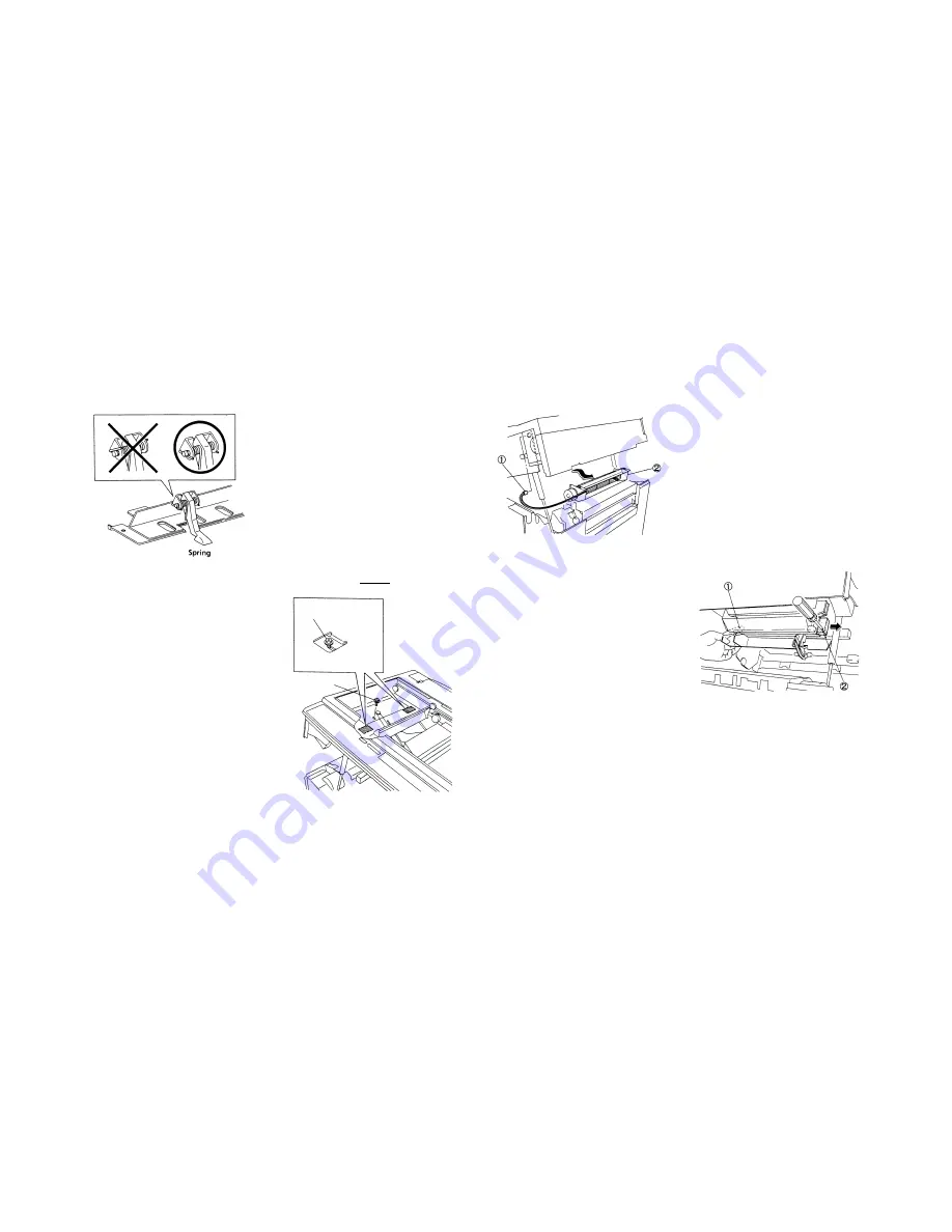
8. Fuser
Installation
1. Perform the installation in the reverse order of
removal.
NOTE
:
•
(Fig. 7): Install the Finger with the both
ends of the Spring under the Shaft.
(Fig. 7)
8.5.1 Fuser Fan Motor Assembly
Replacement
Removal
1.
WARNING:
Power off the machine and
disconnect the
power cord.
2. Remove the Platen Glass. ……............ (4.1.1)
3. Open the Front Cover and then the machine.
4. Remove the Left/Rear Upper Covers.
5. Remove the Drum Unit and place a black
bag over it. ……..,………………………. (5.1.1)
6. Move the Full-Rate Carriage slowly to the
right.
7. (Fig. 1): Loosen the Fuser Fan Motor Assy
Mounting Screw.
NOTE
:
•
(Fig. 2): The Vibration Preventing
Damper Tapes are attached to the
Fan Motor Assy securing areas. If
the screws are not loose enough,
you may not be able to remove the
Fan Motor Assy.
➀
. Loosen Screws enough.
➁
. Remove Screw.
(Fig. 1)
8. (Fig. 2): Remove the Fuser Fan Motor Assy.
➀
. Disconnect P/J409 from Main PWB.
➁
. Remove Fuser Fan Motor Assy.
(Fig. 2)
Installation
1. Perform the installation in the reverse order of
removal.
CAUTION
:
•
Put the shock absorber of the Fan
Motor. Assy against the Ozone
Filter securely.
8.5.2 Ozone Filter(Fuser Fan)
Replacement
Removal
1.
WARNING:
Power off the machine and
disconnect the power cord.
2. Open the Front Cover and then the machine.
3. (Fig. 1): Remove the Ozone Filter.
➀
. Put the Filter at front by pushing the rear
end of the Ozone Filter.
NOTE
:
•
When you can’t push out the Filter by
Step
➀
, remove the Fuser Fan Motor
Assy. ……………………......... (8.5.1)
➁
. Using the screwdriver in an upright position,
prise out the Ozone Filter.
NOTE
:
•
When removing the Ozone Filter
alone without replacing it with a new
one, do not use Step
➁
.
Remove the Filter by removing the
Fuser Fan Motor Assy instead.
(Fig. 1)
Installation
1. Insert the new Filter into the area from which
the old one has been removed.
➁
➀
Summary of Contents for 5915
Page 4: ...Section 1 Service Procedure ...
Page 6: ...1 2 Section 1 Service Procedure 1 1 Precautions Intentional bank page ...
Page 9: ...Section 2 Troubleshooting ...
Page 12: ...2 3 Section 2 Troubleshooting Intentional blank page ...
Page 35: ...Section 4 Disassembly Assembly Adjustment ...
Page 37: ...4 2 Section 4 Disassembly Assembly Adjustment Intentional blank page ...
Page 76: ...Section 5 Parts List ...
Page 110: ...Section 6 GENERAL ...
Page 123: ...Section 7 Wiring Data ...
Page 130: ...7 7 Connector Configuration Section 7 WIRING DATA R H VIEW A A DETAILS TOP VIEW Fig 6 Fig 7 ...
Page 131: ...7 8 Section 7 Wiring Data Connector Configuration TOP VIEW Fig 8 BASE FRAME TOP VIEW Fig 9 ...
Page 132: ...Section 9 BSD Block Schematic Diagram ...
Page 135: ...9 3 1 1 STANDBY POWER Section 9 BSD Block Schematic Diagram ...
Page 136: ...9 4 Section 9 BSD Block Schematic Diagram 1 1 STANDBY POWER ...
Page 137: ...9 5 1 1 STANDBY POWER Section 9 BSD Block Schematic Diagram ...
Page 139: ...9 7 3 1 OPTICS Section 9 BSD Block Schematic Diagram ...
Page 141: ...9 9 4 PAPER SUPPLYING AND TRANSPORTATION Section 9 BSD Block Schematic Diagram ...
Page 143: ...9 11 5 XEROGRAPHICS COPY TRANSPORTATION AND FUSING Section 9 BSD Block Schematic Diagram ...


