


6-7
6.5 Installation/Removeal
Section 6 GENERAL
6.5 Installation/Removal
6.5.1 Installation
XEROX 5915
Installation Procedure
Note
: To comply IEC 950, IEC 950 Brackets
(YJ-68) is required as mandatory.
See procedure No 9.
1. Introduction
•
Tick (V) the ”Check column of the table below
as you proceed with the installation.
Note
: Prepare the Phillips head screwdriver (
⊕
).
2. Check accessories (in the accessory box)
Check
Name
Qty
User guide
1
Copy Output Tray
1
Tray Pad
1
Paper
1
Drum Cover (Black plastic bag)
1
Service Record Card
1
Warranty record
1
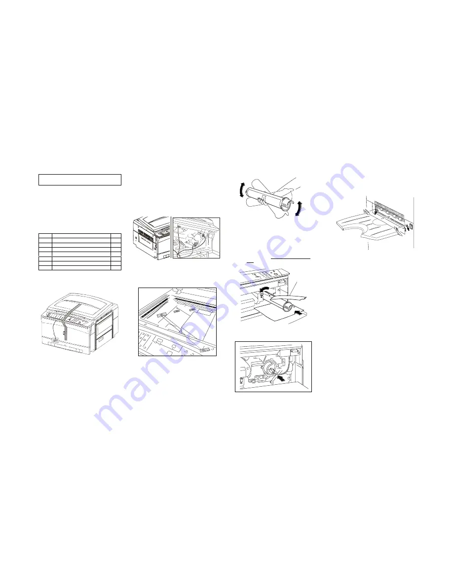
3. Remove the Tape
1) Peel off the tapes from the main
Processor.
4. Remove the Packing material that secures the
part.
1) Remove the cushion from fuser exit.
2) Open the Front Cover, then open the
machine.
3) Pull the label to remove the packing
material from the four areas of the
machine.
4) Close the machine.
5. Peel off the tapes from the optical area.
(air ship only)
6. Load the toner Cartridge.
1) Open the Front Cover.
2) Spread a sheet of paper to protect the
back of the cover from toner spillage.
3) Remove the dummy Cartridge (tube)
toward the front side. Put the it in the
empty box for disposal.
4) Shake the Toner Cartridge more than 10
times.
5) Fit the claw of the new Toner Cartridge to
the groove and push the Cartridge. Pull
the tape towards you & remove. Place in
the empty box for disposal.
6) Press in the Toner Cartridge as much as
possible, then turn it counterclockwise
until it clicks.
7) Press in the Toner Cartridge and engage
the ID socket on to the cartridge
7. Install the Copy Output Tray.
1) Set the Copy Output Tray by placing the
protrusion on the arrow make of the main
processor.
8. Turn on the power switch.
1) Make a copy from each tray .
2) Check that no paper is jammed and copy
image quality is good.
9. Perform the Operator Initial Training Program.
Tape
Summary of Contents for 5915
Page 4: ...Section 1 Service Procedure ...
Page 6: ...1 2 Section 1 Service Procedure 1 1 Precautions Intentional bank page ...
Page 9: ...Section 2 Troubleshooting ...
Page 12: ...2 3 Section 2 Troubleshooting Intentional blank page ...
Page 35: ...Section 4 Disassembly Assembly Adjustment ...
Page 37: ...4 2 Section 4 Disassembly Assembly Adjustment Intentional blank page ...
Page 76: ...Section 5 Parts List ...
Page 110: ...Section 6 GENERAL ...
Page 123: ...Section 7 Wiring Data ...
Page 130: ...7 7 Connector Configuration Section 7 WIRING DATA R H VIEW A A DETAILS TOP VIEW Fig 6 Fig 7 ...
Page 131: ...7 8 Section 7 Wiring Data Connector Configuration TOP VIEW Fig 8 BASE FRAME TOP VIEW Fig 9 ...
Page 132: ...Section 9 BSD Block Schematic Diagram ...
Page 135: ...9 3 1 1 STANDBY POWER Section 9 BSD Block Schematic Diagram ...
Page 136: ...9 4 Section 9 BSD Block Schematic Diagram 1 1 STANDBY POWER ...
Page 137: ...9 5 1 1 STANDBY POWER Section 9 BSD Block Schematic Diagram ...
Page 139: ...9 7 3 1 OPTICS Section 9 BSD Block Schematic Diagram ...
Page 141: ...9 9 4 PAPER SUPPLYING AND TRANSPORTATION Section 9 BSD Block Schematic Diagram ...
Page 143: ...9 11 5 XEROGRAPHICS COPY TRANSPORTATION AND FUSING Section 9 BSD Block Schematic Diagram ...


