background image

19

20

A T TA C H M E N T

The cutter is shipped partially assembled. Assembly will

be easier if components are aligned and loosely assem-
bled before tightening hardware. Recommended torque
values for hardware are located on page 26.

Select a suitable working area. Refer to illustrations,

accompanying text, parts lists and exploded view
drawings.

Complete check lists on page 20 when assembly is

complete.

Position cutter flat and cut the nylon straps that are

holding all loose parts to the cutter.

Rotate the “A” frame hitch forward and connect lift arms

and toplink.

Attach the two linkage lift straps to the cutter deck

(behind the gearbox) and to the end of the slack link on
the “A” frame. These bolted connections are moveable
joints – so tighten nylock nuts only until excess loose-
ness is gone.

Most swinging drawbars will have to be moved to a

forward position or removed.  Check the tractor swing-
ing drawbar for interference with the front of the cutter
before attempting to lift the cutter with the 3-pt. hitch.

Tractor lift arm stabilizer bars or sway blocks must be

used to control side movement of the cutter.  DO NOT
CONNECT THE PTO DRIVELINE AT THIS TIME.

Check your lift arm hydraulic controls.  Be sure the

hydraulic 3-pt. hitch control is in the float position and the
draft control is turned off.

Adjust lower lift arm(s) to level cutter right to left.  Refer

to tractor operator’s manual for instructions.

Cutting height is controlled with tractor 3-point arms,

and rear tailwheel adjustment.

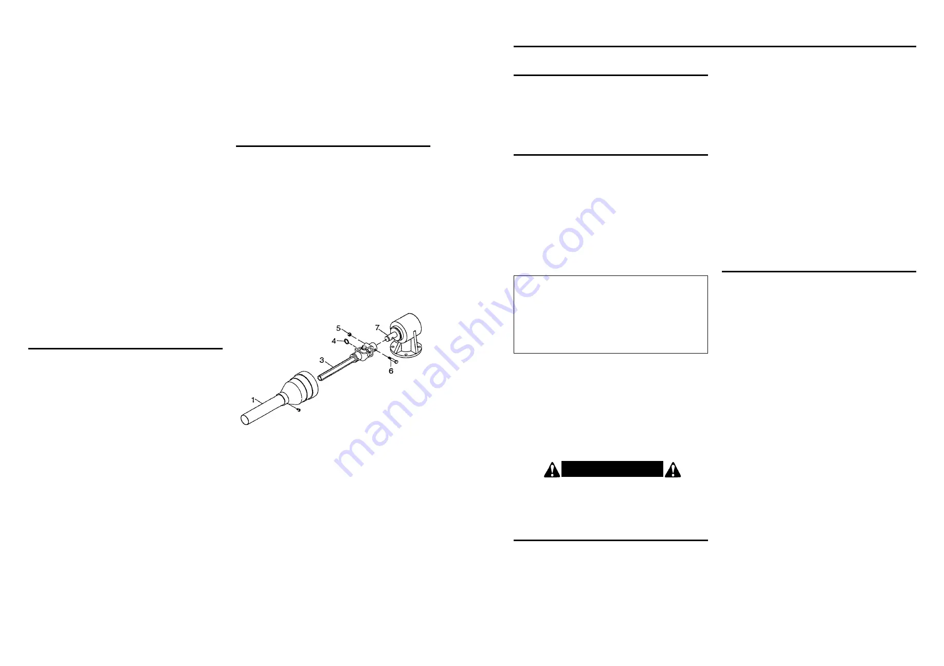
PTO DRIVELINE INSTA L L AT I O N

Spray WD-40 into the yoke and wipe. This should

remove some of the paint and make it easier to slide the
yoke onto the input shaft of the gearbox.

Remove shearbolt and retaining ring (4) from gearbox

input shaft (3).

Grease the input shaft of the gearbox before installing

the PTO shaft. This reduces the chance of the PTO shaft
yoke from galling to the input shaft if the shear pin should
break.

Remove rear drive shield (1) from driveline. To remove,

turn each plastic clip 

1

/

4

turn and then lift out. Then slide

rear shield so entire joint assembly is exposed. (Refer to
figure 5.)

To prevent seal damage, carefully push driveline onto

gearbox input shaft until it contacts gearbox housing.

Install retaining ring (4) and then pull driveline ahead.

NOTE:  A grade 2 bolt must be used for the shear bolt
to provide gearbox protection.

Align the holes in the driveline yoke and gearbox input

shaft and install and tighten shear bolt (6) and nut (5).

Install rear drive shield to driveline.

Lubricate rear driveline half and install front driveline

half.

I N S T R U C T I O N S  

(continued)

1. Drive shield
3. Input driveline shaft half
4. Retaining ring
5. Nut
6. Shearbolt grade 2  

1

/

2

– 13 NC x 3” long

7. Gearbox

Figure 5. Shear Bolt Driveline Installation

Adjust the tailwheel and lift arms so the cutter is level.

Then raise the tractor lift very slowly, making sure that
the front drive shaft shield does not hit the front of the
cutter.  If it does, damage will be done to the drive shaft
shield and, if interference is bad enough, it WILL also
damage the drive shaft itself.

NOTE:  This type of damage is NOT covered under
warranty, as it is totally under the control and the
responsibility of the operator.

Use the lift control limiting stop on the tractor control

lever to limit the upward travel of the lever so the lift can-
not be raised high enough to cause contact between the
drive shaft shield and front shielding.

7. Check the swinging drawbar of the tractor and make

sure the PTO driveline assembly will not contact.  The
swinging drawbar can be moved forward on some
tractors or it can be removed.  

If the PTO driveline assembly contacts the swinging

drawbar, damage will occur to the driveshaft shield and
possibly the driveshaft itself. (NOT covered under
warranty.)

O P E R AT I N G   I N S T R U C T I O N S

Safety is a primary concern in the design and

manufacture of our products. Unfortunately, our efforts
to provide safe equipment can be wiped out by a
single careless act of an operator.

It has been said, “The best safety device is an

informed, careful operator”.  We ask you to be that
kind of an operator.

The designed and tested safety of this machine

depends on it being operated within the limitations as
explained in this manual.  Be familiar with and follow all
safety rules in the manual, on the cutter and on the
tractor.

The safe operation of this machine is the responsibility of

the owner/operator.  The operator should be familiar with
the cutter and tractor and all safety practices before start-
ing operation.  Read the safety rules on pages 4 thru 14.

always tilt the cutter slightly lower in the front. This tilt
decreases horsepower requirements. When fine shred-
ding is desired, adjust cutter deck level or slightly lower.
This will keep the foliage under cutter until thoroughly
shredded. More power is required for shredding.

The cutting height is adjustable from 1 - 5 inches. To

adjust, proceed as follows:

A. Raise cutter off ground using tractor 3-point lift.  Turn

off tractor engine, disengage PTO, set parking brake,
and remove key from ignition.

B. SECURELY BLOCK CUTTER.

C. Remove bolt securing tailwheel to adjusting strap.

D. Adjust tailwheel to desired position. Secure with bolt,

lockwasher and nut.

E. Lower cutter to work position.

F. Adjust tractor 3-point hitch top link so linkage lift straps

have a small amount of slack to allow cutter deck to
float during operation.

GEARBOX OIL FILL

NOTE: The gearbox is shipped WITHOUT lubricant, so it
will be necessary to fill is before use. With the gearbox in
a level position, fill to the side inspection hole with a good
90 wt. gear lubricant. Check often and add lubricant if
necessary.

A D J U S T I N G   F O R   W O R K

The cutter should be operated at the highest position

which will give desired cutting results.  This will help pre-
vent the blades from striking the ground, reducing blade
wear and undue strain on the machine.  For best results 

G E N E R A L   S A F E T Y

Only qualified people familiar with this manual should

operate this machine.  Operator should wear hard hat,
safety glasses, and safety shoes.  It is recommended
that tractor be equipped with Roll-Over Protective
System (ROPS) and a seat belt be used.  Before begin-
ning operation, clear work area of objects that may be
picked up and thrown.  Check for ditches, stumps, holes,
or other obstacles that could upset tractor or damage
cutter.  Always turn off tractor engine, set parking brake,
lower cutter to ground and allow cutter blades to come to
a complete stop before dismounting tractor.

P R E - O P E R AT I O N   C H E C K L I S T

(OWNER RESPONSIBILITY)

____ Review and follow safety rules and safety signs on

pages 4 through 16.

____ Check that cutter is properly and securely attached

to tractor.

____ Make sure driveline spring-activated locking pin or

locking balls operate freely and are seated firmly in
tractor PTO spline groove.

____ Lubricate all grease fitting locations. Make sure

PTO shaft slip joint is lubricated.

____ Check to be sure gear lube runs out the small

check plug on side of gearbox.

____ Check that all hardware is properly installed.

____ Check to ensure blades are sharp and secure and

cutting edge is positioned to lead in a counter-
clockwise rotation.

____ Check that all shields and guards are properly

installed and in good condition.

____ Check cutting height, front to rear attitude and top

link adjustment.

____ Place tractor PTO and transmission in neutral

before starting engine.

____ Set tractor PTO gear select lever for 540 rpm

operation.

____ Inspect area to be cut and remove stones,

branches or other hard objects that might be
thrown, causing injury or damage.

C A U T I O N !

Do not operate the PTO at other than the rated 540

RPM.  Excessive speeds can cause breakage, thrown
objects, and potential injury.

Summary of Contents for SDM40-48

Page 1: ... front as well as the rear when working with the implement OWNER S OPERATOR S MANUAL MODEL NO s SDM40 48 SDM40 60 SDM40 72 WHEN ORDERING REPAIR PARTS ALWAYS GIVE THE FOLLOWING INFORMATION 1 PART NUMBER 2 PART DESCRIPTION 3 MODEL NUMBER 4 NAME OF ITEM OCTOBER 2001 WS RM002 OG W O R K S AVER INC P O BOX 100 LITCHFIELD IL 62056 0100 217 324 5973 WEB http www worksaver com E MAIL sales worksaver com E...

Page 2: ...erator s responsibility to inspect the product and to have any part s repaired or replaced when continued operation would cause damage or excessive wear to other parts or cause a safety hazard It is the Retail Customer s responsibility to deliver the product to the authorized Worksaver Dealer from whom he purchased it for service or replacement of defective parts which are covered by warranty Repa...

Page 3: ... 1 1 92 1 1 47 Input RPM 540 RPM 540 RPM Output RPM 1036 8 RPM 793 8 RPM Gearbox Warranty Limited 1 Year Gearbox Lubrication 90 wt Gear Oil PTO Driveline Type Metric Series 4 Total Driveline Length Closed 32 37 43 Shearbolt 1 2 Diameter x 3 0 Bolt Grade 2 Blades Number Type 2 Suction Type Width Thickness 1 2 x 3 Length Total 18 25 30 Tip Speed 12 757 Ft Min 12 255 Ft Min 15 170 Ft Min Blade Carrie...

Page 4: ... Check all blade beam bolts h Check cutter attitude after mounting on tractor h Check that gearbox is properly serviced and seals are not leaking h Check shear bolt for proper grade and installation h Check front of input gearbox shaft and make sure that snap ring is properly installed h All safety signs decals in place and readable h When the cutter is transported on a road or highway at night or...

Page 5: ...tructed in safe and proper use The use of this equipment is subject to certain hazards which cannot be protected against by mechanical means or product design All operators of this equipment must read and understand this entire manual paying particular attention to safety and operating instructions prior to using If there is something in this manual you do not understand ask your supervisor or you...

Page 6: ... this machine while taking prescription medications Review the safety instructions with all users annually This equipment is dangerous to children and persons unfamiliar with its operation The operator should be a responsible adult familiar with farm machinery and trained in this equipment s operations Do not allow persons to operate or assemble this unit until they have read this manual and have ...

Page 7: ... in place Small air pockets can be pierced with a pin and smoothed out using the piece of sign backing paper Failure to follow proper procedures when mounting a tire on a wheel or rim can produce an explosion which may result in serious injury or death Do not attempt to mount a tire unless you have the proper equipment and experience to do the job Inflating or servicing tires can be dangerous When...

Page 8: ... other than yourself is loaned or rented to make certain that the operator prior to operating 1 Reads and understands the operator s manuals 2 Is instructed in safe and proper use SAFETY TRAINING Do not allow children to operate this machine PTO SHAFT SHEAR BOLT PROTECTED PA RTS VIEW PA RTS LIST REF WORKSAVER E G NO NO PART NO PART NO DESCRIPTION REQ D 650565 07 422 117 10 Complete Driveline Assem...

Page 9: ... Replacement or repair parts installed in the equipment covered by this warranty are warranted for ninety 90 days from the date of purchase of such part or to the expiration of the applicable new equipment warranty period whichever occurs later Such parts shall be provided at no cost to the user during regular working hours Worksaver reserves the right to inspect any equipment or parts which are c...

Page 10: ...being run over by the cutter Accidents are most likely to occur with machines that are loaned or rented to someone who has not read the owner s manual and is not familiar with a rotary cutter Check the tractor master shield over the PTO stub shaft Make sure it is in good condition and fastened securely to the tractor Purchase a new shield if old shield is damaged or missing You may have to use a t...

Page 11: ...ks and securely fastened Many varied objects such as wire cable rope or chains can become entangled in the operating parts of the cutter head These items could then swing outside the housing at greater velocities than the blades Such a situation is extremely hazardous Inspect the cutting area for such objects before mowing Removing any like object from the site Never allow the cutting blades to co...

Page 12: ...heel weights front tractor weight and or tire ballast should be used to improve stability Be careful when operating tractor and cutter on uneven ground to avoid upsetting Pass diagonally through sharp dips and avoid sharp drops to prevent hanging up tractor and cutter Practice will improve your skills in maneuvering rough terrain Avoid sudden starts and stops while traveling up or downhill Always ...

Page 13: ...machines Use a safety chain to prevent unexpected separation with pull type models TRANSPORT SAFETY TROUBLESHOOTING GUIDE P R O B L E M POSSIBLE CAUSE POSSIBLE REMEDY Leaves a streak of uncut 1 Cutter not level side to side Level 3 pt hitch linkage on tractor or partially cut grass 2 Blades dull or bent Sharpen or replace blades 3 Carrier RPM too low Use correct PTO speed 4 Field conditions are so...

Page 14: ... all persons away from operator control area while performing adjustments service or maintenance Frequently check cutter blades They should be sharp free of nicks and cracks and securely fastened Periodically tighten all bolts nuts and screws and check that all cotter pins are properly installed to ensure unit is in a safe condition When completing a maintenance or service function make sure all s...

Page 15: ...g area MAINTENANCE SAFETY continued STORAGE SAFETY BLADE BEAM GEARBOX INSTA L L ATION A Raise cutter using tractor 3 point lift Turn off tractor engine B BLOCK CUTTER SECURELY INTO POSITION C Remove cotter pin and blade holder retaining nut Wear heavy work gloves to protect hands from sharp edges D Grasp blade holder and pull off shaft If necessary align blade bar with access hole in top of deck a...

Page 16: ...nsert lockwasher 2 and nut 1 through blade access hole in the cutter deck install on bolt 5 and tighten to 350 lbs ft Repeat for opposite blade Sharpen both blades at the same time to maintain bal ance Follow original sharpening pattern Do not sharpen blade to a razor edge but leave at least a 1 16 blunt edge Do not sharpen back side of blade Rotate blade beam 3 and repeat for opposite blade Alway...

Page 17: ...lic system leakdown and failure of mechanical or hydraulic system can cause equip ment to drop Keep all persons away from operator control area while performing adjustments service or mainte nance LUBRICATION INFORMATION Figure 6 shows the lubrication points The accompany ing chart gives the frequency of lubrication in operating hours based on normal conditions Severe or unusual conditions may req...

Page 18: ...tices before starting operation Read the safety rules and safety signs on pages 4 16 This standard duty cutter is designed for grass and weed mowing and shredding Recommended mowing speed for most conditions is from two to five mph T R A N S P O RTING Pay particular close attention to the Safety Messages regarding cutter transport Avoid unnecessary injuries and equipment damage by exercising cauti...

Page 19: ...g ing PTO position cutter in a cut area and reduce tractor throttle to idle If cutter continuously stalls select lower tractor gear and or increase cutting height Blade rotation is counterclockwise causing cut material to discharge to the left side of cutter forming a windrow To shred and dissipate this windrow tractor should be driven in a counterclockwise direction throwing material to the uncut...

Page 20: ... under warranty O P E R ATING INSTRUCTIONS Safety is a primary concern in the design and manufacture of our products Unfortunately our efforts to provide safe equipment can be wiped out by a single careless act of an operator It has been said The best safety device is an informed careful operator We ask you to be that kind of an operator The designed and tested safety of this machine depends on it...

Page 21: ... under warranty O P E R ATING INSTRUCTIONS Safety is a primary concern in the design and manufacture of our products Unfortunately our efforts to provide safe equipment can be wiped out by a single careless act of an operator It has been said The best safety device is an informed careful operator We ask you to be that kind of an operator The designed and tested safety of this machine depends on it...

Page 22: ...g ing PTO position cutter in a cut area and reduce tractor throttle to idle If cutter continuously stalls select lower tractor gear and or increase cutting height Blade rotation is counterclockwise causing cut material to discharge to the left side of cutter forming a windrow To shred and dissipate this windrow tractor should be driven in a counterclockwise direction throwing material to the uncut...

Page 23: ...tices before starting operation Read the safety rules and safety signs on pages 4 16 This standard duty cutter is designed for grass and weed mowing and shredding Recommended mowing speed for most conditions is from two to five mph T R A N S P O RTING Pay particular close attention to the Safety Messages regarding cutter transport Avoid unnecessary injuries and equipment damage by exercising cauti...

Page 24: ...lic system leakdown and failure of mechanical or hydraulic system can cause equip ment to drop Keep all persons away from operator control area while performing adjustments service or mainte nance LUBRICATION INFORMATION Figure 6 shows the lubrication points The accompany ing chart gives the frequency of lubrication in operating hours based on normal conditions Severe or unusual conditions may req...

Page 25: ...nsert lockwasher 2 and nut 1 through blade access hole in the cutter deck install on bolt 5 and tighten to 350 lbs ft Repeat for opposite blade Sharpen both blades at the same time to maintain bal ance Follow original sharpening pattern Do not sharpen blade to a razor edge but leave at least a 1 16 blunt edge Do not sharpen back side of blade Rotate blade beam 3 and repeat for opposite blade Alway...

Page 26: ...g area MAINTENANCE SAFETY continued STORAGE SAFETY BLADE BEAM GEARBOX INSTA L L ATION A Raise cutter using tractor 3 point lift Turn off tractor engine B BLOCK CUTTER SECURELY INTO POSITION C Remove cotter pin and blade holder retaining nut Wear heavy work gloves to protect hands from sharp edges D Grasp blade holder and pull off shaft If necessary align blade bar with access hole in top of deck a...

Page 27: ... all persons away from operator control area while performing adjustments service or maintenance Frequently check cutter blades They should be sharp free of nicks and cracks and securely fastened Periodically tighten all bolts nuts and screws and check that all cotter pins are properly installed to ensure unit is in a safe condition When completing a maintenance or service function make sure all s...

Page 28: ...machines Use a safety chain to prevent unexpected separation with pull type models TRANSPORT SAFETY TROUBLESHOOTING GUIDE P R O B L E M POSSIBLE CAUSE POSSIBLE REMEDY Leaves a streak of uncut 1 Cutter not level side to side Level 3 pt hitch linkage on tractor or partially cut grass 2 Blades dull or bent Sharpen or replace blades 3 Carrier RPM too low Use correct PTO speed 4 Field conditions are so...

Page 29: ...heel weights front tractor weight and or tire ballast should be used to improve stability Be careful when operating tractor and cutter on uneven ground to avoid upsetting Pass diagonally through sharp dips and avoid sharp drops to prevent hanging up tractor and cutter Practice will improve your skills in maneuvering rough terrain Avoid sudden starts and stops while traveling up or downhill Always ...

Page 30: ...ks and securely fastened Many varied objects such as wire cable rope or chains can become entangled in the operating parts of the cutter head These items could then swing outside the housing at greater velocities than the blades Such a situation is extremely hazardous Inspect the cutting area for such objects before mowing Removing any like object from the site Never allow the cutting blades to co...

Page 31: ...being run over by the cutter Accidents are most likely to occur with machines that are loaned or rented to someone who has not read the owner s manual and is not familiar with a rotary cutter Check the tractor master shield over the PTO stub shaft Make sure it is in good condition and fastened securely to the tractor Purchase a new shield if old shield is damaged or missing You may have to use a t...

Page 32: ... Replacement or repair parts installed in the equipment covered by this warranty are warranted for ninety 90 days from the date of purchase of such part or to the expiration of the applicable new equipment warranty period whichever occurs later Such parts shall be provided at no cost to the user during regular working hours Worksaver reserves the right to inspect any equipment or parts which are c...

Page 33: ... other than yourself is loaned or rented to make certain that the operator prior to operating 1 Reads and understands the operator s manuals 2 Is instructed in safe and proper use SAFETY TRAINING Do not allow children to operate this machine PTO SHAFT SHEAR BOLT PROTECTED PA RTS VIEW PA RTS LIST REF WORKSAVER E G NO NO PART NO PART NO DESCRIPTION REQ D 650565 07 422 117 10 Complete Driveline Assem...

Page 34: ... in place Small air pockets can be pierced with a pin and smoothed out using the piece of sign backing paper Failure to follow proper procedures when mounting a tire on a wheel or rim can produce an explosion which may result in serious injury or death Do not attempt to mount a tire unless you have the proper equipment and experience to do the job Inflating or servicing tires can be dangerous When...

Page 35: ... this machine while taking prescription medications Review the safety instructions with all users annually This equipment is dangerous to children and persons unfamiliar with its operation The operator should be a responsible adult familiar with farm machinery and trained in this equipment s operations Do not allow persons to operate or assemble this unit until they have read this manual and have ...

Page 36: ...tructed in safe and proper use The use of this equipment is subject to certain hazards which cannot be protected against by mechanical means or product design All operators of this equipment must read and understand this entire manual paying particular attention to safety and operating instructions prior to using If there is something in this manual you do not understand ask your supervisor or you...

Page 37: ... Check all blade beam bolts h Check cutter attitude after mounting on tractor h Check that gearbox is properly serviced and seals are not leaking h Check shear bolt for proper grade and installation h Check front of input gearbox shaft and make sure that snap ring is properly installed h All safety signs decals in place and readable h When the cutter is transported on a road or highway at night or...

Page 38: ... 1 1 92 1 1 47 Input RPM 540 RPM 540 RPM Output RPM 1036 8 RPM 793 8 RPM Gearbox Warranty Limited 1 Year Gearbox Lubrication 90 wt Gear Oil PTO Driveline Type Metric Series 4 Total Driveline Length Closed 32 37 43 Shearbolt 1 2 Diameter x 3 0 Bolt Grade 2 Blades Number Type 2 Suction Type Width Thickness 1 2 x 3 Length Total 18 25 30 Tip Speed 12 757 Ft Min 12 255 Ft Min 15 170 Ft Min Blade Carrie...

Page 39: ...erator s responsibility to inspect the product and to have any part s repaired or replaced when continued operation would cause damage or excessive wear to other parts or cause a safety hazard It is the Retail Customer s responsibility to deliver the product to the authorized Worksaver Dealer from whom he purchased it for service or replacement of defective parts which are covered by warranty Repa...

Page 40: ... front as well as the rear when working with the implement OWNER S OPERATOR S MANUAL MODEL NO s SDM40 48 SDM40 60 SDM40 72 WHEN ORDERING REPAIR PARTS ALWAYS GIVE THE FOLLOWING INFORMATION 1 PART NUMBER 2 PART DESCRIPTION 3 MODEL NUMBER 4 NAME OF ITEM OCTOBER 2001 WS RM002 OG W O R K S AVER INC P O BOX 100 LITCHFIELD IL 62056 0100 217 324 5973 WEB http www worksaver com E MAIL sales worksaver com E...

Reviews: